Hi all,
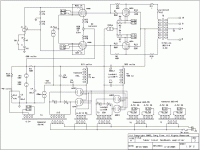
Gary Pimm's Tabor looks - and should sound no doubt - very impressive but it goes too much for me... So I thought to simplify it down to the absolutely essentials and the result is the attached schematic. It is just calculations on paper and designed around some tubes I already have and it was a real puzzle to make it "work" electricaly before anything else. Add to this that I haven't done pentodes before so please show mercy reading the circuit explanation.
There are no stacked psus nor tube rectifiers not tube voltage stabilizers either. Only one psu but with a J. Broskie's trick; a voltage divider that rises the circuit ground so that the negative rail stays 10V bellow ground. Tested on a preamp, it works fine! So I have some headroom for the input stage CCS. This CCS is copied from one of Allen Wright's designs but I'm not sure if it will work here as well, so if you please have a look at this. The screens' regulated supply is again copied from Valve Wizard's website. I've used it in another circuit and seems to work fine!
Having not used the complex psu of the original design leaves a significant amount of power to be dissipated on the output stage CCS. Modern power mosfets can handle this but they would need serious heatsinks, and I didn't want my amp to look like a satellite. So, I thought to use a tube CCS as I have a couple of EL34.
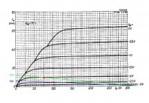
To put all these together I ended up to the operating points shown bellow. The equation goes like this; the higher the voltage on EF86 plates, the higher the voltage on 6P31S cathodes, the higher the power dissipation on EL34, and I don't want to go very high... I set the max limit for EL34 at 20W.
I would really appreciate your opinions on this. It would be interesting to know if it worths to build it.
Thanks in advance!
Gary Pimm's Tabor looks - and should sound no doubt - very impressive but it goes too much for me... So I thought to simplify it down to the absolutely essentials and the result is the attached schematic. It is just calculations on paper and designed around some tubes I already have and it was a real puzzle to make it "work" electricaly before anything else. Add to this that I haven't done pentodes before so please show mercy reading the circuit explanation.
There are no stacked psus nor tube rectifiers not tube voltage stabilizers either. Only one psu but with a J. Broskie's trick; a voltage divider that rises the circuit ground so that the negative rail stays 10V bellow ground. Tested on a preamp, it works fine! So I have some headroom for the input stage CCS. This CCS is copied from one of Allen Wright's designs but I'm not sure if it will work here as well, so if you please have a look at this. The screens' regulated supply is again copied from Valve Wizard's website. I've used it in another circuit and seems to work fine!
Having not used the complex psu of the original design leaves a significant amount of power to be dissipated on the output stage CCS. Modern power mosfets can handle this but they would need serious heatsinks, and I didn't want my amp to look like a satellite.
So, I thought to use a tube CCS as I have a couple of EL34.To put all these together I ended up to the operating points shown bellow. The equation goes like this; the higher the voltage on EF86 plates, the higher the voltage on 6P31S cathodes, the higher the power dissipation on EL34, and I don't want to go very high... I set the max limit for EL34 at 20W.
I would really appreciate your opinions on this. It would be interesting to know if it worths to build it.
Thanks in advance!
Attachments
Thanks for replies!
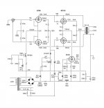
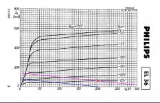
All voltages are refered to ground. Some points have negative voltage with respect to ground. Still, I may have done mistakes. I also thought about EF184 and I made some calculations. How small the driver's load resistor can be? Is there any limit with respect to OPT's impedance? EL36 is the equivalent of 6P31S if that is what you ask. I used a mosfet CCS where it could fit and a tube where the mosfet would had a hard time.Many voltages are wrong.
You need another tube then a EF86, more a EF184 to get some gain.
Why on one side a mos CS and a EL36 (34?) ?
Mona
Do you mean a cap from screen to cathode like in all pentode applications?Also, the EL34's screen MUST be decoupled capacitively to its cathode for a proper operation as pentode. Again, decoupled to cathode, not to ground.
Attachments
Do you mean a cap from screen to cathode like in all pentode applications?
Exactly. Although with other objective, but take a reading at this pdf.
Attachments
Another thing is that the voltage swing is rather fixed here. The driver's plate voltage at idle has to be around 130V. We can only play with current. If this isn't enough then the project has to be reconsidered drasticaly....
You need another tube then a EF86, more a EF184 to get some gain.
...
Mona
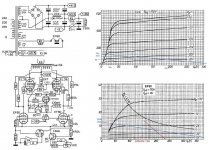
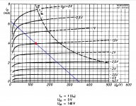
The amp has to function in classA (CCS on cathodes).The TS proposed 60mA bias current (12W Pa) what gives an anode current between 0 and 120mA.Is there a reason the load line is so much below the knee for the EL36?
Mona
Mona,
This is far more than I could ask! Many, many thanks! I can understand what I see in your schematic everything except the 39k resistors from B+ in parallel with the EF80 anode resistors. Perhaps to avoid interaction with the OPT? Also, the output CCS now gets only 0,65W(?). the rest 28W where are going?
This is far more than I could ask! Many, many thanks! I can understand what I see in your schematic everything except the 39k resistors from B+ in parallel with the EF80 anode resistors. Perhaps to avoid interaction with the OPT? Also, the output CCS now gets only 0,65W(?). the rest 28W where are going?
I just tried to follow what I thought Gary Pimm did. Class A within SoA and be able to swing the whole voltage coming from the drivers since there is 100% feedback meaning -to my mind - unity gain.Is there a reason the load line is so much below the knee for the EL36?
Got it! There are no 28W. It works like a stacked psu isn't it?Mona,
Also, the output CCS now gets only 0,65W(?). the rest 28W where are going?
Exactly, 170V at screens. Cathodes at 220V and screens at 390V, anodes at 415V meaning 195V anode to cathode.That's only valid for Vg2 = 170V, not sure what you mean by 100% feedback...
100% feedback is what Tabor supposed to do with its coupling scheme.
Sorry, made a mistake 
I took the hole swing of the powertube anode, must be from operating point to one end = half. Anode from 195V to 35V with grid 25V to15V, so the voltage gain is ~17x.
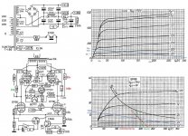
With a resistor 56k between grid and anode the driver sees not 56k but only 56/16=3k5. Now we need a swing of 10volts up an down for the grid that is ~3mA.(with my error 6mA).If the EF80 runs 5mA it has to go up to 8 and down to 2mA, with a rather non linear response. And with 5mA the drop on 56k is 280V, can not be, has to be a smaller resistance = more feedback current = still higher EF80 current.Like that we get nowhere.Solution is higher resistance to anode power tube and another one to the +power for more current.I used 220k + 39k to get 195V with 6,8mA anode EF80.
Since the gain isn't 35 but 17x it can be 100k and 47k for the same result.
Mona
I took the hole swing of the powertube anode, must be from operating point to one end = half. Anode from 195V to 35V with grid 25V to15V, so the voltage gain is ~17x.
With a resistor 56k between grid and anode the driver sees not 56k but only 56/16=3k5. Now we need a swing of 10volts up an down for the grid that is ~3mA.(with my error 6mA).If the EF80 runs 5mA it has to go up to 8 and down to 2mA, with a rather non linear response. And with 5mA the drop on 56k is 280V, can not be, has to be a smaller resistance = more feedback current = still higher EF80 current.Like that we get nowhere.Solution is higher resistance to anode power tube and another one to the +power for more current.I used 220k + 39k to get 195V with 6,8mA anode EF80.
Since the gain isn't 35 but 17x it can be 100k and 47k for the same result.
Mona
No need to apologize...Sorry, made a mistake
But isn't it odd to have a grid swing of just 20Vp-p for the EL36's, seems wasteful. That's why I found the Vg2 = 170V choice puzzling, wouldn't it be better to lower the screen voltage to get a better load line? In any case, the EL36's aren't really the best choice for Class A, they are more suited for Class AB1.Yes, there is local negative feedback, but it does not work as "100% feedback", the final stage still has gain.100% feedback is what Tabor supposed to do with its coupling scheme.
Here it is with corrections (and perhaps no other mistakes ).Also showing two versions, with and without the extra anode resistance to the +power (green as the original, red with extra)
You can see the big difference in current swing at the EF80 for ±10V out.
And yes, the EL36 is capable of much more, but here are the limitations of the classA, the low power voltage and 5k OPT.
Mona
).Also showing two versions, with and without the extra anode resistance to the +power (green as the original, red with extra)You can see the big difference in current swing at the EF80 for ±10V out.
And yes, the EL36 is capable of much more, but here are the limitations of the classA, the low power voltage and 5k OPT.
Mona
Attachments
I see, I was not aware that the PS or the OPT were set in stone, I thought it was a clean-sheet design. Anyway, I don't think the EL36's are actually operating in Class A (even on a restricted grid swing of just 20Vp-p), as the tubes still reach cut-off (or very close to it).And yes, the EL36 is capable of much more, but here are the limitations of the classA, the low power voltage and 5k OPT.
Mona
If anyone needs to apologize, that's me for my limited understanding on electronics. But given the chance I need to ask some things.
Trying to find some information about how Tabor works I got a fractional picture for the feedback mechanism. It helped me to see it like a direct coupled cathode follower. I didn't thought that the output stage draws current from the drivers, especialy since the EL36 grids would never come close to zero, but instead the power tubes would steal the whole voltage from the drivers thus at the output there would be only the drivers gain. I thought that the voltage headroom at the cathodes of the power tubes plays a significant role. Perhaps it would help me to understand it better if I could have an explanation about Mona's calculations for the feedback resistor. (220k/35)//39k and then 56k/16k=3k5. From where do the numbers 35 and 16k derive?
The 170V at the screens was the lowest I found on the datasheet. I guess lower would be better.
I realy enjoy advanced theory, even if I can't follow thoroughly. I just hope I'm not being boring!
- Status
- This old topic is closed. If you want to reopen this topic, contact a moderator using the "Report Post" button.
- Home
- Amplifiers
- Tubes / Valves
- Poor Man's TABOR