Using a CCS tail under P-P output tubes in class A produces a gm sum that is like a big bump. See the E55L curves below, page 9, for the gm ("S" curve) versus current. (typical for all tubes) (two complementary oriented curves get summed for P-P, summing to a big bump in the middle)
Then see page 5 for the grounded cathode version of gm curves versus grid voltage drive. (typical for all tubes) These form an S shape which sums closer to a constant gm in class A P-P (complementary curves summed).
With the gm bump from a CCS tail scheme, strong odd harmonics are generated with compressive effects at larger amplitudes. Allen Wright discovered this and had to put a resistor in the tail to lower the cathode impedance.
Unless you like compressed sound, this Tabor scheme is just a hard way to make compressed distortion. Far easier to design it right (no CCS tail for outputs).
https://frank.pocnet.net/sheets/009/e/E55L.pdf
Yes, there is even some "optimal" Rtail of approx. 1/gm (gm sum of both tubes in class A) which will minimize 3rd harmonic over some signal range. You would have to watch the FFT while adjusting it. (may only work for triodes, not sure, there is an article about it online somewhere and on DIYaudio. ) (not working well for class AB)
By the way, 25HX5, is the same as E235L (and EL36, 6P31S) but with NO plate cap and 14 Watt (design max.) Pdiss.
21HB5A gets you the same plate curve set, using 2/3 the Vg2, and 18 Watt Pdiss (design max., and a plate that's as big as some 24 Watt tubes).
6GB5, EL500, EL504 and variants are very close to the 21HB5A, for plate curves.
Using the 14000 gm spec (at 100 mA) for EL36, then doubling that for two in class A, gives an Rtail of 36 Ohms. (approx. ballpark range) A little higher Rtail than that with more reasonable class A idle currents.
Last edited:
3rd harmonic cancellation paper by M.V. Kiebert and P.R. Mallory Co.
https://www.diyaudio.com/forums/tub...h3-3rd-harmonic-cancellation.html#post4571822
https://www.diyaudio.com/forums/tub...h3-3rd-harmonic-cancellation.html#post4571822
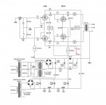
The way this amp is designed, 6P31S cathodes are some 55W away from ground. "Vref" is there to relief the CCS from 50 of those. I was thinking to substitute the CCS for a 91ohm/10W resistor -from cathodes to Vref- for a quick test. I can't see how a smaller resistor could work, for classA always. What do I miss?
The direct coupling would require a re-do of the voltage levels in order to use a small resistor there. However, the resistor is only important for AC distortion compensation, so you could try connecting a low value resistor (or adjustable pot) in series with a big cap across the CCS ( or just from cathodes to ground) to see if you get any improvement in "sound" or distortion level.
If that helps, then a re-design without the CCS tail should allow you to get more Watts out too.
If that helps, then a re-design without the CCS tail should allow you to get more Watts out too.
Last edited:
Done! I used a 100 ohm wirewound pot and a 220μ cap. Nice thing to see it changing in front of your eyes! The best I could do is attached. It's at 1W to compare with post #54. Considerable improvement. However the max power has not been increased and still reaches the limit in the same hard way. The pot's position? 8 0hm!?
Attachments
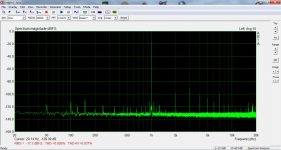
Happy New Year everyone! I've been playing with the cathode resistor tweak these days but nothing came out. The results at post #70 are valid only for 1kHz. A THD vs freq plot revealed a distortion havoc at lower frequencies. I thought to change the cap from 220μ to 10m and then the trim pot only affected H2 leaving H3 intact. I managed to null completely H2 at 52 ohm but again only for 1kHz fundamental. I read Kiebert-Mallory paper -here's a link that works https://pearl-hifi.com/06_Lit_Archive/02_PEARL_Arch/Vol_01/Sec_01/065_Dsgn_Fctrs_for_PwrAmps.pdf . I can only superficially understand it but if it works by injecting distortion in opposite phase to be cancelled, perhaps it can't act together with the feedback mechanism of this amp? I'm not the one to answer that, I only know that it works with quite heavy feedback and it got already better when I reduced it.
- Status
- This old topic is closed. If you want to reopen this topic, contact a moderator using the "Report Post" button.
- Home
- Amplifiers
- Tubes / Valves
- Poor Man's TABOR