The Tabor is a pretty advanced design even though it appears quite simple. ") The output stage is an i-to-v amplifier, not a cathode follower. The conversion ratio is set by the feedback resistor - the exact calculation can be found on Tubecad's website, look under "partial feedback amplifier".
The output stage is an i-to-v amplifier, not a cathode follower. The conversion ratio is set by the feedback resistor - the exact calculation can be found on Tubecad's website, look under "partial feedback amplifier".
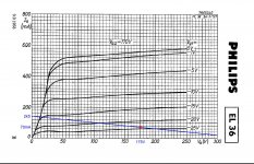
As for the EL36's, here is a more workable load line using a much lower screen voltage (100V) and lower primary impedance (3ka-a):

The output stage is an i-to-v amplifier, not a cathode follower. The conversion ratio is set by the feedback resistor - the exact calculation can be found on Tubecad's website, look under "partial feedback amplifier".As for the EL36's, here is a more workable load line using a much lower screen voltage (100V) and lower primary impedance (3ka-a):
Well, with a bias current of 60mA the cathodes CCS has to be 120mA.If one side goes to zero there is only 120mA left for the other side, not chance to go further up to 176mA.Kindly elaborate.
Mona
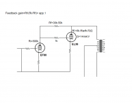
I'm trying hard. Please have a look at the schematic. Since EF80 Ri is too high (0,5M) then the closed loop gain of the EL36 using a resonable range of feedback resistors should be approximately 1. Of course, I may be wrong. Please correct me. The rest of my thinking is based on this. A variation of 1V at EL36 plate would mean 1V at its grid. Its transconductance will then effectively reduce Ri' so 1V be retained at the plate. It's supposed that what comes in that goes out or not?
The EF80 should have a Zout app equal to the feedback resistor and have to face the same Zload isn't it? If so, what requirements does this set for the driver?
Edit: According to my thinking the EF80 would have to provide the whole gain/ voltage swing which proved untrue in previous posts.
The EF80 should have a Zout app equal to the feedback resistor and have to face the same Zload isn't it? If so, what requirements does this set for the driver?
Edit: According to my thinking the EF80 would have to provide the whole gain/ voltage swing which proved untrue in previous posts.
Attachments
Last edited:
you'll need a+215 +585v and -60v solid state power supply to duplicate this amp
I like the EL34 used as the output tubes current source.
you could use a 100 VA 120 to 120 CT tranformer and use a voltage doubler to 585v and bridge to 215v. A diode and smaller cap ( 2.2uf/ 400v ) from secondary would yield the -60v @ 10ma
3 transistors as cap multipliers to replace the inductors and you're done.
Last edited:
Ok, I did my homework. Although I had came accross J. Broskie's article More Hybrid-Amplifier DesignIonly got it superficially back then. Now I was able to understand it a little deeper I think. I also found this thread Partial Feedback Amplifiers where Gary Pimm himself explains the basics about Tabor. Funny thing at some point the possibility that EF86 might be better than 6AU6 is dicussed because it might have a higher transconductace at the particular operating point, something that is not obvious from the datasheets. Anyway, I would like to stick with Mona's schematic.
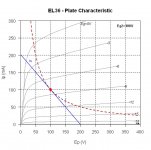
First of all, I moved the operation point of the output tube to 175V/70mA keeping the 5k a-a OPT so now it is a little more center biased. It should swing a little more voltage this way. Please, keep in mind I actualy use 6P31S which has a little different specs from EL36, only 10W plate dissipation but I rely on that it's a TV tube - plus it's cheap.
So, 175V B+ and app 160V voltage swing with 25V swing on the grid. That should mean 185V swing accross the feedback resistor (Rfb). Rfb is also the load of the driver EF80. I didn't manage to understand Mona's calculations and Broskie doesn't give a direct coupled example. So, a little voodoo to get a resistor not too big if it is to swing no more than B+ and not too small either to be a heavy load for the driver. 33k should take 5,6mA to swing 185v, and at idle it should have 415V at one side and 215V at the other (415 - 175Vplate to cathode of 6P31S - 25Vbias). That is 6mA through Rfb at idle.
So, EF80 operates at 415V B+ with 33k load (?) and 215V plate voltage at 6mA at idle. And it should be able to swing 5,6mA which if it does then Rfb will see from 13V-382V(?) I guess the green load line demonstrates how +/-5mA swing at EF80 plate will give +/-25V at 6P31S grid.
Have I missed something? Or perhaps did I get any of this right?
http://www.tubecad.com/march2001/
Attachments
Thanks Jazbo8! I understand the non optimal operating point of the output tube. I wouldn't insist on anything. All parameters could be adjusted at will. If not +/- 25V at the grid then how much is it? It is -25 to 0 from one side and less from the other I suppose but how to find this?
Looks good, seems you get the feel of it.
The swing on the grid isn't 25V, goes between 15 and 25V, is 10Vtop or 20Vtt.
That is a voltage gain ~16x nd the EF80 "sees" 2k (33/2=16,5)
You need then 10/2=5mAtop from the EF80.1mA to 11mA is rather non linear.
With a resistor, not to the anode but, to the +power you can turn-up the current without extra the load.As an exemple,another 33k to + gives (6+6)mA in the EF80 and up and down 7...17mA, much smaller ratio, less distortion.
By playing with the ratio between those two resistors you can pick a suitable compromise.
Mona
Thanks Mona! Everything understood exept this;
How do we find this?...the EF80 "sees" 2k (33/2=16,5)
Mona
If the grid)side of the 33k feedback resistor goes +10V (to -15V) the anode-side goes down 150V.Total voltage change on the resistor 160V.The driver feels with the 10V change a 160/10 times more change then to be expected from 33k, as if there is a 16 times smaller resistor (=~2k).I wrote 33/2=16,5 to say 2k is a close enough of the 33/output gain value (no need to go into decimals).
Mona
Mona
In other words it could be said that the driver sees the input impedance of the I/V stage; Zin= (1/gm+Rfb)/(gain+1)=1945 ohm, Right?If the grid)side of the 33k feedback resistor goes +10V (to -15V) the anode-side goes down 150V.Total voltage change on the resistor 160V.The driver feels with the 10V change a 160/10 times more change then to be expected from 33k, as if there is a 16 times smaller resistor (=~2k).I wrote 33/2=16,5 to say 2k is a close enough of the 33/output gain value (no need to go into decimals).
Mona
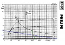
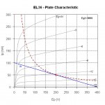
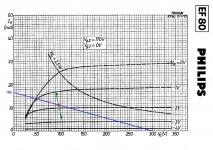
Playing with these curves, there is something that should work with B+ 200V and 4k a-a OPT (first pic). I don't know if the second one is usable, 100V B+ and 2k a-a OPT. That would allow to bias the driver as in third pic. One thing to add is that since both stages are differential amps, 2nd order harmonic distortion should not be a big issue anyway.Back to the grid swing issue - even though the load line shown in post #21 isn't correct, you can still use the Ep-Ip chart to come up with a more conventional load line which should also reduce the distortion of the output stage.
Attachments
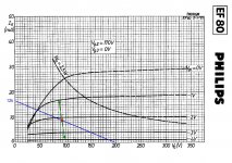
I forgot to say that in case we use the second scheme then we need 100v B+ for the power tubes and 300V for the drivers. It is the only way I can see to work so that the driver could swing a good ratio idle/peak current. The problem is that the tail CCS of the power stage would have to dissipate some 40W. With a symmetrical psu of 0/150V/300V watts could go down to 10. Is it possible to use unequal PT secondaries to get 0/200V/300V?
- Status
- This old topic is closed. If you want to reopen this topic, contact a moderator using the "Report Post" button.
- Home
- Amplifiers
- Tubes / Valves
- Poor Man's TABOR