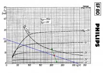
A little more work on this. Of course, the only reason to move from Mona's schematic is to explore different operating points. Searching for EL36, I found that it has been used in SE OTL amps with high impedance speakers, 1k or even 600 0hm. And datasheet typical characteristics are 100V plate voltage at 100mA when it's biased at -8,2V just like the load line in post #37. Then EF80 will be biased as above. I tried to apply all this in a new schematic.
I would like to ask if this psu would work. No CT secondary, it has to be two windings. Have I got right the power ratings? If so, then for 150V/50mA x2 100V/350mA x2 6,3V/4A x2 would be 135VA. A local manufacturer can do this at a reasonable cost.
I would like to ask if this psu would work. No CT secondary, it has to be two windings. Have I got right the power ratings? If so, then for 150V/50mA x2 100V/350mA x2 6,3V/4A x2 would be 135VA. A local manufacturer can do this at a reasonable cost.
Attachments
Update
Happy new year everyone!
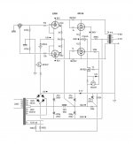
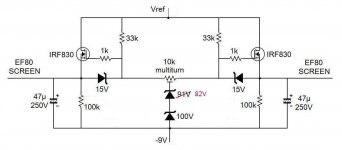
I found the time to work on some ideas. Before anything, Mona's design is excellent but it was based on the suboptimal operating point for the power stage that I had originaly set. Nevertheless, the one transformer psu is all the money and I' ll keep it for some other tubes that may fit better. For EL36/6P31S the 100V/100mA to plate, 100V to g2 seems much better so I went for this. EF80 plate won't settle on 92V as said in the previous post, it should be 192V of course. In any case, the higher the quiescent current of the driver, the higher the peak current it will be, so this tube will always operate in the non linear range. That is with a single feedback resistor. Mona suggested the parallel load resistors which I' m willing to try but since I can only do listening evaluation, this will take time. For the record, J. Broskie - speaking for SE with partial feedback - suggests to compensate the drivers distortion with the I/V stage distortion. Gary Pimm reduced distortion by inserting highish value resistors as screen grid stoppers - at the cost of reduced transcoductance. I guess he could measure significant distortion destite this is a differential amp. That's bad news, I was comfortably relying on distortion cancelation.
Anyway, after digesting the theory a little better, I put it all down to a new schematic. The "audio" circuit was the easy part. For the psu I had an idea based on common parts that are not listed in vendors' "audiophile" catalogues. I already had a 12V/150VA toroid salvaged from old halogen lights that proved to have two secondaries in parallel. One for the power tubes' heaters referred to 220V and the other for the drivers referred to ground. Two small 12V/12VA transformers connected back to back to get the lower B+ (Vref). And for the upper B+, an isolation transformer for domestic use - 230V to 2x115V/100VA. This one is marginal I ought to say as it has to work at 100% of its nominal rating. At the moment it just gets slightly warm, but it's winter. I' ll be watching it. Finally, I used fluorescent lamp ballasts as chokes. They measure 1H so I built a CLCLC filter. Whole lotta iron for little money! And B+ is low so capacitors are cheap.
OPT need to be 2k a-a. One could use power transformers for that. If my calculations are right, a 2x115V to 12V should do for 8 ohm speakers. But I wanted to give it a desent chance so I ordered a pair from Toroidy. There went half the budget of the project.
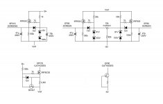
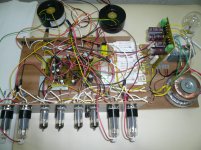
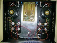
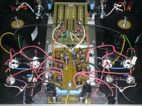
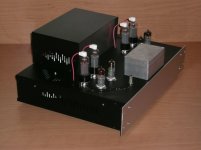
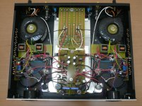
I' ve built a prototype to find out if it works at all. One thing brought another and it ended up to the nightmare of the photo. The upright pcb is the B+. The other one under the forest holds four CCS and six mosfet voltage regulators. EF80 g2 supply is not exactly regulated as it is referred to a resistor voltage divider but I think it is better stabilized and with lower AC impedance. Again, me thinks... As mentioned above, Gary Pimm deliberately increased the impedance here and I could always do the same by taking the pot before the screens. Since I was there I did thae same for the power tubes too.
I also did a little internet reading about CCS. My conclusion is that when the current gets above a couple of mA, then cascoded designs take over to give exceptional performance up to some 50 mA. From there on things are quite different, and at 214 mA reliability is mostly what we can ask for. It must be said that I haven't found Gary Pimm's schematics though. I took what Mona suggested. I used IRF830 - I had it - which has lower capacitance when Vds>25V. That means 5,35W on the heatsink. Currently, Vds is around 15V. 3,2W. I' ll see about that later. After all, this is a tail CCS, it faces a low impedance. Same approach for the drivers with a single jfet. I' m still working on this. At the moment I use LM317.
So, does it work? I get the right voltage everywhere and nothing smoked. And it delivers sound! But it is noisy, ground loop buzzing and the alike. I' m not surprisad given this mess. This prototype was built just to verify the electrical operation. Bias adjustment works as intented, quite stable on one channel, continiously drifting on the other. And needs fine adjustment at every start up. To me it has to do with noise and oscillations. Things improved when I connected EF80 internal shields to ground. Well, I got myself here now, so a chassis with proper wiring is what left to do. I have the feeling that the problem will be addressd in the final implementation.
That - much - said, I hope you' ll take the time to read it. I would very much appreciate any advice before I move on.
Happy new year everyone!
I found the time to work on some ideas. Before anything, Mona's design is excellent but it was based on the suboptimal operating point for the power stage that I had originaly set. Nevertheless, the one transformer psu is all the money and I' ll keep it for some other tubes that may fit better. For EL36/6P31S the 100V/100mA to plate, 100V to g2 seems much better so I went for this. EF80 plate won't settle on 92V as said in the previous post, it should be 192V of course. In any case, the higher the quiescent current of the driver, the higher the peak current it will be, so this tube will always operate in the non linear range. That is with a single feedback resistor. Mona suggested the parallel load resistors which I' m willing to try but since I can only do listening evaluation, this will take time. For the record, J. Broskie - speaking for SE with partial feedback - suggests to compensate the drivers distortion with the I/V stage distortion. Gary Pimm reduced distortion by inserting highish value resistors as screen grid stoppers - at the cost of reduced transcoductance. I guess he could measure significant distortion destite this is a differential amp. That's bad news, I was comfortably relying on distortion cancelation.
Anyway, after digesting the theory a little better, I put it all down to a new schematic. The "audio" circuit was the easy part. For the psu I had an idea based on common parts that are not listed in vendors' "audiophile" catalogues. I already had a 12V/150VA toroid salvaged from old halogen lights that proved to have two secondaries in parallel. One for the power tubes' heaters referred to 220V and the other for the drivers referred to ground. Two small 12V/12VA transformers connected back to back to get the lower B+ (Vref). And for the upper B+, an isolation transformer for domestic use - 230V to 2x115V/100VA. This one is marginal I ought to say as it has to work at 100% of its nominal rating. At the moment it just gets slightly warm, but it's winter. I' ll be watching it. Finally, I used fluorescent lamp ballasts as chokes. They measure 1H so I built a CLCLC filter. Whole lotta iron for little money! And B+ is low so capacitors are cheap.
OPT need to be 2k a-a. One could use power transformers for that. If my calculations are right, a 2x115V to 12V should do for 8 ohm speakers. But I wanted to give it a desent chance so I ordered a pair from Toroidy. There went half the budget of the project.
I' ve built a prototype to find out if it works at all. One thing brought another and it ended up to the nightmare of the photo. The upright pcb is the B+. The other one under the forest holds four CCS and six mosfet voltage regulators. EF80 g2 supply is not exactly regulated as it is referred to a resistor voltage divider but I think it is better stabilized and with lower AC impedance. Again, me thinks... As mentioned above, Gary Pimm deliberately increased the impedance here and I could always do the same by taking the pot before the screens. Since I was there I did thae same for the power tubes too.
I also did a little internet reading about CCS. My conclusion is that when the current gets above a couple of mA, then cascoded designs take over to give exceptional performance up to some 50 mA. From there on things are quite different, and at 214 mA reliability is mostly what we can ask for. It must be said that I haven't found Gary Pimm's schematics though. I took what Mona suggested. I used IRF830 - I had it - which has lower capacitance when Vds>25V. That means 5,35W on the heatsink. Currently, Vds is around 15V. 3,2W. I' ll see about that later. After all, this is a tail CCS, it faces a low impedance. Same approach for the drivers with a single jfet. I' m still working on this. At the moment I use LM317.
So, does it work? I get the right voltage everywhere and nothing smoked. And it delivers sound! But it is noisy, ground loop buzzing and the alike. I' m not surprisad given this mess. This prototype was built just to verify the electrical operation. Bias adjustment works as intented, quite stable on one channel, continiously drifting on the other. And needs fine adjustment at every start up. To me it has to do with noise and oscillations. Things improved when I connected EF80 internal shields to ground. Well, I got myself here now, so a chassis with proper wiring is what left to do. I have the feeling that the problem will be addressd in the final implementation.
That - much - said, I hope you' ll take the time to read it. I would very much appreciate any advice before I move on.
Attachments

Thanks jazbo8. I' m already planing to finalize it with a better layout. You may laugh with my way to draw schematics. I use windows XP pain(t) and a library of symbols that I took from here and there. There is specialized free software for this job but when schematics become too big the symbols and the letters get very small for my weak vision.
Hi Mona,
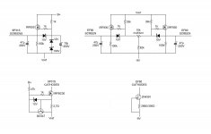
The zeners stay "off". There isn't enough voltage to bias them. I measure around 185V at mosfet gates (175V from ground) and 172V (from ground) to the screens. I can adjust the screen voltage roughly from 165 to 178V. I found it out by trial and error, it is difficult to calculate the current in this circuit. The zeners were left as a safety in case of pot's failure and as an option to bias the mosfets if I have to move the pot to the screens. No problem to try your scheme of course.
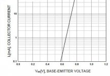
There is another thing I need to ask about the output stage CCS. I tried to find out how it works and my understanding is that BC547 must reach Vbe "on". That is 0,6V according to datasheet. This is what you use in your schematic : 0,6V/4,7ohm=130mA. I read different numbers in my circuit. Vbe is 0,45V, actually I use a 2 ohm resistor to get 225mA. Seems to work but is this OK?
The zeners stay "off". There isn't enough voltage to bias them. I measure around 185V at mosfet gates (175V from ground) and 172V (from ground) to the screens. I can adjust the screen voltage roughly from 165 to 178V. I found it out by trial and error, it is difficult to calculate the current in this circuit. The zeners were left as a safety in case of pot's failure and as an option to bias the mosfets if I have to move the pot to the screens. No problem to try your scheme of course.
There is another thing I need to ask about the output stage CCS. I tried to find out how it works and my understanding is that BC547 must reach Vbe "on". That is 0,6V according to datasheet. This is what you use in your schematic : 0,6V/4,7ohm=130mA. I read different numbers in my circuit. Vbe is 0,45V, actually I use a 2 ohm resistor to get 225mA. Seems to work but is this OK?
You'r quite right, by conducting the transistor try to cutoff the fet, but that leads to not conducting of the transistor.The battle stops somewhere in between with Vbe a little over 600mV (the 100k on the collector gives Ic=~1mA) over the low ohmic resistor.There is another thing I need to ask about the output stage CCS. I tried to find out how it works and my understanding is that BC547 must reach Vbe "on". That is 0,6V according to datasheet. This is what you use in your schematic : 0,6V/4,7ohm=130mA. I read different numbers in my circuit. Vbe is 0,45V, actually I use a 2 ohm resistor to get 225mA. Seems to work but is this OK?
If you measure 0,45V there is a bad transistor or a bad measurement.
Mona
Attachments
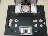
I was planning to finish it this weekend but I feel exhausted. Job entered peak season unexpectedly earlier this time. Anyway, only the pcb with the regs and CCSs is left to install. I tried for the best lay out I could. I think heaters wiring should be OK. I'm worrying about those fluorescent ballasts EMI. We'll see.
I found a couple of 2N4391 that seem suitable for the EF80 CCS. The source resistor can only be found by experimentation. One of them takes 270 ohm (Vgs=4,96V) and the other 300 ohm (Vgs=5,52V). Both at Vdg=11,5V. I hope they will do. I can always rise Vdg for a few volts with the zeners.
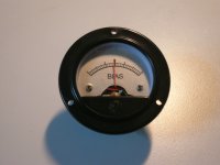
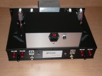
I installed the bias potensiometers externally to be used with panel meters. Since the total current of the output tubes is fixed by the CCS, I only need to measure the difference between the cathodes, and that should be 0V. I thought to use a "center 0" millivoltmeter like galvanometers but the only one I found is insanely prised. So I bought two inexpensive ordinary voltmeters and I modified them. There is a lock nut that allows to move the needle's rest position. I scaned the back panel, changed it and printed on metalized self adhesive labels. I also changed the internal compensating resistor to make it a 350mV meter from center to end. Now the total resistanse of the meter is 795 0hm. Would this be OK across the cathodes or is it to low? Should I place the meter across a high resistanse voltage divider?
I found a couple of 2N4391 that seem suitable for the EF80 CCS. The source resistor can only be found by experimentation. One of them takes 270 ohm (Vgs=4,96V) and the other 300 ohm (Vgs=5,52V). Both at Vdg=11,5V. I hope they will do. I can always rise Vdg for a few volts with the zeners.
I installed the bias potensiometers externally to be used with panel meters. Since the total current of the output tubes is fixed by the CCS, I only need to measure the difference between the cathodes, and that should be 0V. I thought to use a "center 0" millivoltmeter like galvanometers but the only one I found is insanely prised. So I bought two inexpensive ordinary voltmeters and I modified them. There is a lock nut that allows to move the needle's rest position. I scaned the back panel, changed it and printed on metalized self adhesive labels. I also changed the internal compensating resistor to make it a 350mV meter from center to end. Now the total resistanse of the meter is 795 0hm. Would this be OK across the cathodes or is it to low? Should I place the meter across a high resistanse voltage divider?
Attachments
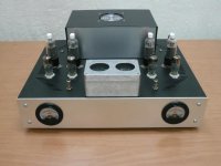
Thanks to your contribution, I'm happy to report I have a new amplifier!
Most of this stuff was new to me: pentodes, partial feedback, mosfet regulators and not least top plate caps. Tidying up the wiring revealed a severe oscillation due to stray capacitance of the plate caps/wires. It was stealing the Vbe of the BC547 in the output stage CCS (?) and half the voltage from the 9,1V zeners used for the negative supply (??) It was not easy for me to troubleshoot. It took a lot of sniffing around and an accidental finding in another thread. Now I know what does this "selected" R12 in Gary Pimm's schematic mean. Since I don't know how to select it, I used a 10 ohm 3W. For a quick test I used a common cement wirewound and it cured the problem completely. The next day I returned to make it "better" and used a metal film but it didn't work. I read about carbon composition resistors for grid stoppers. What is suitable for plates? Anyway I have the wirewound for now. I also removed the zeners that were not necessary and increaced the load to the rest. Updated schematics with actual operating points attached.
I was worrying about the behaviour of the amp connected to my sensitive speakers. I was expecting at least nasty noise at power up. This is not the case. Although there is a bias chaos for a while, nothing comes out from the speakers. The amp comes to life in a very civilized manner and I cannot tell if it works with my ear touching the speakers. Those are 94db/W/m speakers. The 6P31S seems very tough. Initialy it will take 200% its max power dissipation without sweat. I remember a EL34 in another amp going red plate at once! A few seconds later the current settles at a difference of some 30mA between the two tubes and from there on it will gradually go to zero adjusted from previous time. It always get it, no need for rebias at every power on. The potensiometers allow perfect adjustment but the analog meters I was planning to use although working cannot be used for accuracy below 10mA. I guess I'll have to live with LCDs on the front panel.
How does it sound is the question. Output power is 7W per channel. Speakers have to be big. Mine are as said. Even so, the amp will take a lot of input signal to move them. Probably because the input stage is not working as a typical voltage amplifier. I had to make some tricks to adjust the gain structure of my system and I have some more to do but the amp already shows what it can do. My sonic evaluation standards are very simple: the bass should affect other senses more than hearing, the treble should serve for the bass to be audible and the mids should provide information for the recording ambience. My new amp sounds very good.")
Long post reflecting my enthousiasm. Winter's project went well!
Most of this stuff was new to me: pentodes, partial feedback, mosfet regulators and not least top plate caps. Tidying up the wiring revealed a severe oscillation due to stray capacitance of the plate caps/wires. It was stealing the Vbe of the BC547 in the output stage CCS (?) and half the voltage from the 9,1V zeners used for the negative supply (??) It was not easy for me to troubleshoot. It took a lot of sniffing around and an accidental finding in another thread. Now I know what does this "selected" R12 in Gary Pimm's schematic mean. Since I don't know how to select it, I used a 10 ohm 3W. For a quick test I used a common cement wirewound and it cured the problem completely. The next day I returned to make it "better" and used a metal film but it didn't work. I read about carbon composition resistors for grid stoppers. What is suitable for plates? Anyway I have the wirewound for now. I also removed the zeners that were not necessary and increaced the load to the rest. Updated schematics with actual operating points attached.
I was worrying about the behaviour of the amp connected to my sensitive speakers. I was expecting at least nasty noise at power up. This is not the case. Although there is a bias chaos for a while, nothing comes out from the speakers. The amp comes to life in a very civilized manner and I cannot tell if it works with my ear touching the speakers. Those are 94db/W/m speakers. The 6P31S seems very tough. Initialy it will take 200% its max power dissipation without sweat. I remember a EL34 in another amp going red plate at once! A few seconds later the current settles at a difference of some 30mA between the two tubes and from there on it will gradually go to zero adjusted from previous time. It always get it, no need for rebias at every power on. The potensiometers allow perfect adjustment but the analog meters I was planning to use although working cannot be used for accuracy below 10mA. I guess I'll have to live with LCDs on the front panel.
How does it sound is the question. Output power is 7W per channel. Speakers have to be big. Mine are as said. Even so, the amp will take a lot of input signal to move them. Probably because the input stage is not working as a typical voltage amplifier. I had to make some tricks to adjust the gain structure of my system and I have some more to do but the amp already shows what it can do. My sonic evaluation standards are very simple: the bass should affect other senses more than hearing, the treble should serve for the bass to be audible and the mids should provide information for the recording ambience. My new amp sounds very good.
Long post reflecting my enthousiasm. Winter's project went well!
Attachments
Last edited:
Update!
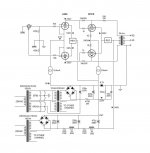
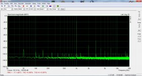
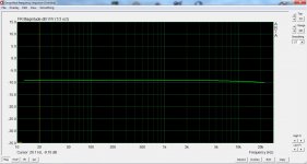
This amp started from nothing...and zero knowledge too. It was an attempt to explore this scheme keeping the budget low. If nothing else, I enjoyed the learning curve. This does not mean that I'm not satisfied by the amp. On the contrary, it has very interesting qualities one of them being the low end authority. OTOH, I felt that it was struggling to perform. Too low gain, and only marginally stable. Obviously the feedback was too heavy for those tubes both drivers and finals. So, I split the driver's load resistor as suggested previously. I used 47k for the feedback resistor and 22k coming from B+. Also, I found a new PT, same concept as previously -a cheap isolation transformer- but double VA so it runs cooler and with better regulation thus B+ increased by 10V. Updated schematic is attached. The amp now is more relaxed with higher gain and lower distortion. I attach some basic measurements taken with simplistic equipment just to give you an idea. These are at 1W output. The amp is usable up to 5-6W, then distorts severely. It requires sensitive speakers and in my case I enjoy plenty of volume at half a watt, the rest left for headroom.
Another feature of this amp is that it's completely noiseless even at turn on. You can only tell it's alive when it starts playing music. The output tubes will be out of bias balance for some minutes before they get warm but nothing reaches the speakers.
Speaking of bias... At turn on, it is not unusual to see one output tube -and primary winding- taking the whole current, and not just instantly. 230mA!!! But no red plating or magic smoke occurred so far. Then, it will gradually find its balance as set last time. But this will happen only if the load hasn't been changed i.e. for different speakers or resistive dummy load for measurements requires rebiasing. Bias off balance is not audible. No noise as already said but also no distortion. I've played by altering the bias "on the fly" while measuring distortion and it didn't change anything. However, I stayed within reasonable limits for this experiment. Anyway, there is the necessity for DC cancellation so, panel meters to work with the already exposed bias pots were mandatory. And it would be good to measure anode current rather than cathode so to leave screens out of the equation. Finally, I got the idea from Pete Millett's Isolated Current Sensor I used the same circuit on home etched PCBs and diy current sensors using this https://p.globalsources.com/IMAGES/PDT/SPEC/440/K1139513440.pdf and some small ferrite E-I cores with 50 turns of 0,8mm motor wire. Additionally, I placed one layer of masking tape between the two halves to form an "air gap" just in case. It does 0,6mV/mA enough for my purpose. The meters are described at post #49. I removed the internal resistor completely for max sensitivity. It doesn't measure absolute values, only the relative balance down to 1mA. Calibrated per instructions and works like a charm.
No more ideas for this amp. I think I'll let it be.
This amp started from nothing...and zero knowledge too.
It was an attempt to explore this scheme keeping the budget low. If nothing else, I enjoyed the learning curve. This does not mean that I'm not satisfied by the amp. On the contrary, it has very interesting qualities one of them being the low end authority. OTOH, I felt that it was struggling to perform. Too low gain, and only marginally stable. Obviously the feedback was too heavy for those tubes both drivers and finals. So, I split the driver's load resistor as suggested previously. I used 47k for the feedback resistor and 22k coming from B+. Also, I found a new PT, same concept as previously -a cheap isolation transformer- but double VA so it runs cooler and with better regulation thus B+ increased by 10V. Updated schematic is attached. The amp now is more relaxed with higher gain and lower distortion. I attach some basic measurements taken with simplistic equipment just to give you an idea. These are at 1W output. The amp is usable up to 5-6W, then distorts severely. It requires sensitive speakers and in my case I enjoy plenty of volume at half a watt, the rest left for headroom. Another feature of this amp is that it's completely noiseless even at turn on. You can only tell it's alive when it starts playing music. The output tubes will be out of bias balance for some minutes before they get warm but nothing reaches the speakers.
Speaking of bias... At turn on, it is not unusual to see one output tube -and primary winding- taking the whole current, and not just instantly. 230mA!!! But no red plating or magic smoke occurred so far. Then, it will gradually find its balance as set last time. But this will happen only if the load hasn't been changed i.e. for different speakers or resistive dummy load for measurements requires rebiasing. Bias off balance is not audible. No noise as already said but also no distortion. I've played by altering the bias "on the fly" while measuring distortion and it didn't change anything. However, I stayed within reasonable limits for this experiment. Anyway, there is the necessity for DC cancellation so, panel meters to work with the already exposed bias pots were mandatory. And it would be good to measure anode current rather than cathode so to leave screens out of the equation. Finally, I got the idea from Pete Millett's Isolated Current Sensor I used the same circuit on home etched PCBs and diy current sensors using this https://p.globalsources.com/IMAGES/PDT/SPEC/440/K1139513440.pdf and some small ferrite E-I cores with 50 turns of 0,8mm motor wire. Additionally, I placed one layer of masking tape between the two halves to form an "air gap" just in case. It does 0,6mV/mA enough for my purpose. The meters are described at post #49. I removed the internal resistor completely for max sensitivity. It doesn't measure absolute values, only the relative balance down to 1mA. Calibrated per instructions and works like a charm.
No more ideas for this amp. I think I'll let it be.
Attachments

![EF80 operating point [II].JPG](/community/data/attachments/731/731418-9c1c16e9804bd702666227368404c615.jpg)
Built a series of very similar amps myself. Started with a simple ECL82 headphone amp, then a 6AU6 and 807 power amp, then a series of different 6080 amps. Ended in a 6au6 with PL84 finals. This sits next to me on my workbench semi-retired.
All my designs had front end input transformers biased down to a negative supply such that the plates of the input stage sat at 0V and then directly drove the finals. All sounded very good clean and powerful. However with the tiny gain that this topology develops they are massively inefficient (maybe 1% efficient) which I couldn't live with in the end. Now all digital.
Shoog
I've come across schematics of yours using the input transformer. A nice way to overcome the complexity of the psu. However, the biggest problem is to match drivers and finals properly. I come to think that Gary Pimm's choice was the result of thorough research. The 6au6 seems ideal for this job. And 1624 is easy to drive for the power it can deliver. In any case, this design gives the feeling of a robust buffer mostly. It needs to have enough input sensitivity to accept a good preamp working well past 12 o'clock.
The amp has to function in classA (CCS on cathodes).The TS proposed 60mA bias current (12W Pa) what gives an anode current between 0 and 120mA.
Mona
Anode + Screen current that is. While only anode current goes through the load.
Just a bit to consider, when one side plate voltage is low, and g2 current increases a lot on a per plate voltage drop, what do you think happens?
cheers,
Douglas
Anode + Screen current that is. While only anode current goes through the load.
Just a bit to consider, when one side plate voltage is low, and g2 current increases a lot on a per plate voltage drop, what do you think happens?
cheers,
Douglas
Gary Pimm expressed the opinion that if the screen was taken straight to B+ this was insignificant when in Class A.
This amp has so many levels of self correction that it will produce one of the cleanest lowest impedance signals possible in any design, the price you pay is relatively low power and almost zero overall gain.
Shoog
Last edited:
Shoog, the 6AU6 has one of the highest g2 to anode current ratios. I can tell you that the type EL84 makes a very fine signal amplifier...
So, for a 5k a-a OPT, a 6-pack of EL84 per amp. Two for a LTP, and the four, in PPP. Skip the Schade network, and get an OPT with U-L taps and rig it E-Linear. Plate signal to driver by direct OPT winding fraction, instead of a voltage divider between the plate load and R_fbk. If you can, a 25% U-L tap.
cheers,
Douglas
- Status
- This old topic is closed. If you want to reopen this topic, contact a moderator using the "Report Post" button.
- Home
- Amplifiers
- Tubes / Valves
- Poor Man's TABOR