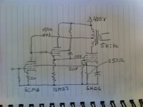
I've been working on this amp for some time. It's a little tricky picking operating points, since I'm working outside the range shown on the data sheets. I wound up having to tweak a few resistors. The values shown are the final design.
The input tube is a 9-pin version of the 6V6. I chose it because it gives what I feel is a reasonable operating point with only 20v on the screen. This allowed me to use a feedback loop from the output tube cathode to the input tube screen, holding operating points stable for DC operation. I nicked this idea from the Mullard 3-3, and use it quite liberally. I like using pentodes as input tubes, especially in DC amps. They work well at lower plate voltages, and have plenty of gain to do the job with one stage.
The output tube is a sweep compactron with the signal fed into the screen grid. I had a few on hand, and I thought it would be fun to try screen-mode operation. I applied bias to the grid to make the screen bias voltage more manageable for DC operation. My design goal here was to use as little grid bias as I could get away with.
The amp employs feedback similar to Schade from the output transformer's UL tap. This is used primarily to lower the output impedance. Screen driven amps are said to be quite linear already. Taking a wild guess at the 6KD6's screen tranconductance, I would say the feedback yields a plate impedance of just under 1kOhm.
Not shown in the schematic is a diode in the cathode follower. It is between the grid and the cathode, and it prevents excessive positive grid voltage as the amp warms up.
On a final note, I think I may have stumbled on a novel form of partial feedback, at least by degrees. It isn't exactly Schade feedback, since that is applied to the grid of the output tube. Ultralinear is applied to the screen, but the screen isn't driven in that scheme. It borrows a bit from E-linear, but, again that doesn't drive the screen. It may have been done before, but screen driven amps seem pretty uncommon, and I haven't seen it.
Attachments
Last edited:
Interesting.
But only 20V on the 6CM6 screen? Must not be running much current there. Another 12HG7 or 12HL7 for input stage could run with good current using the 20V. (and with good V to I linearity from high gm) Looking at screen driven TV sweeps on the curve tracer, I've seen the best linearity when the g1 was near 0V (wrt cathode). Probably something to do with the aligned grids.
The UL tap is usually well coupled to the secondary (as opposed to the plate taps) for UL use, so should work well for N Fdbk, as long as it is stable.
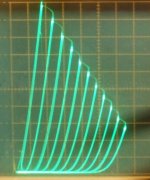
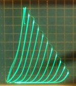
26HU5/6KD6 pics, 50 mA/div Vert, 50V/div Horiz
a) triode Mu of 4
b) Schade gain of 4 approx.
But only 20V on the 6CM6 screen? Must not be running much current there. Another 12HG7 or 12HL7 for input stage could run with good current using the 20V. (and with good V to I linearity from high gm) Looking at screen driven TV sweeps on the curve tracer, I've seen the best linearity when the g1 was near 0V (wrt cathode). Probably something to do with the aligned grids.
The UL tap is usually well coupled to the secondary (as opposed to the plate taps) for UL use, so should work well for N Fdbk, as long as it is stable.
26HU5/6KD6 pics, 50 mA/div Vert, 50V/div Horiz
a) triode Mu of 4
b) Schade gain of 4 approx.
Attachments
Last edited:
I think it was done on purpose to maximize the gain, not the swing.But only 20V on the 6CM6 screen? Must not be running much current there.
It's an interesting variation on a theme. Would you have some measurement data to share? THD, DF, etc.On a final note, I think I may have stumbled on a novel form of partial feedback, at least by degrees.
The 6CM6 is running around 2ma. I considered some higher gm tubes for this position: 6BQ5 or 6HG5A for instance. With 20v on the screen, these tubes would be going into cutoff at less than 1v. I was concerned that grid current could become a problem. The 6CM6 has rather civilized looking transconductance curves with a gradual transition to cutoff. I was able to bias it at 1V and keep it in what I hope is a reasonably linear range of operation. The input tube in this design needs to handle +/- half of its bias current for full output. I like to give it as much breathing room as I can.
Do you have any sweeps where the screen is driven negative? The only thing I could find was Svetlana's data for their version of the EL509. It showed the lines bunching up around 0V.
I'm afraid I haven't invested in anything more advanced than a DVM. My best guess from data sheets is 10-12 watts at 1-2% THD, with DF around 5. I expect the input tube contributes most of the distortion, and that is fairly low ordered. My guess is that for a given percent of feedback, Schade would be more effective than this at reducing distortion and output impedance since transconductance is lower for the screen than the grid. However, screen drive seems more linear than grid drive, so the end results might be close enough.
I've seen the best linearity when the g1 was near 0V (wrt cathode).
Do you have any sweeps where the screen is driven negative? The only thing I could find was Svetlana's data for their version of the EL509. It showed the lines bunching up around 0V.
Would you have some measurement data to share? THD, DF, etc.
I'm afraid I haven't invested in anything more advanced than a DVM. My best guess from data sheets is 10-12 watts at 1-2% THD, with DF around 5. I expect the input tube contributes most of the distortion, and that is fairly low ordered. My guess is that for a given percent of feedback, Schade would be more effective than this at reducing distortion and output impedance since transconductance is lower for the screen than the grid. However, screen drive seems more linear than grid drive, so the end results might be close enough.
Last edited:
I'm afraid I haven't invested in anything more advanced than a DVM. My best guess from data sheets is 10-12 watts at 1-2% THD, with DF around 5. I expect the input tube contributes most of the distortion, and that is fairly low ordered. My guess is that for a given percent of feedback, Schade would be more effective than this at reducing distortion and output impedance since transconductance is lower for the screen than the grid. However, screen drive seems more linear than grid drive, so the end results might be close enough.
Too bad that you don't have a way to test the amplifier... As a comparison, Pete Millett's KT-88 'E-Linear' amplifier does about 15W at 5%, with a DF of 4. The distortion might be lower with your amplifier due to the more linear screen drive, but with lower gmg2 (vs gmg1) and without UL feedback, I suspect the DF is quite a bit lower than what you have indicated and what Pete manages to get from his amplifier. Nevertheless, depending on the source material and the type of speaker used, you may not miss it.
Last edited:
Turns out measuring the damping factor is pretty easy. I came up with a DF of 4. Distortion is a bit more tricky. I played a 1kHz tone through the speakers, and took an RTA measurement with my phone. At 6W I measured harmonics -40dB. I would consider that to have a pretty wide margin for error, though.
I think Pete Millett uses 5% distortion as his definition of clipping. I wonder what distortion was at 10W or so? The measurements posted online don't give the scale, and I don't think I have that issue of AX.
I think Pete Millett uses 5% distortion as his definition of clipping. I wonder what distortion was at 10W or so? The measurements posted online don't give the scale, and I don't think I have that issue of AX.
Turns out measuring the damping factor is pretty easy. I came up with a DF of 4.
Thanks for taking the time to do the measurement. So the DF is on par with the Millett amp, interesting.
bob danielak has an interesting work here...Screen Driven, DC Coupled, Single-ended EL509 Amp
Thanks for running the curves. These make me think it may well be worth the effort to change the output tube to 0v g1 bias. In addition to the clearly more linear operation, my data sheet indicates that the screen would be a bit easier to drive.
I notice the 6KD6 equivalent seems to be the least bad of negative biased sweep tubes. I'm not especially surprised by this. Most sweep tube curves show a hump in the screen current with screen voltage between plate voltage and cutoff for negative grid voltages. The data sheet shows screen current rising more rapidly in this range for the 6KD6, but no hump.
I notice the 6KD6 equivalent seems to be the least bad of negative biased sweep tubes. I'm not especially surprised by this. Most sweep tube curves show a hump in the screen current with screen voltage between plate voltage and cutoff for negative grid voltages. The data sheet shows screen current rising more rapidly in this range for the 6KD6, but no hump.
It seems to be a case of garbage in garbage out, most of Munro's pentode models are not accurate, especially when it comes to the grid or screen current, and your pictures clearly show just how far off the model is vs. reality.The screen drive curve set for that Danielak Screen Drive EL509 looks like a Spice model printout.

It's also a surprise that Svetlana published this article as one of its Techinical Bulletins, you would think the manufacturer of the tube could provide the author with some decent data to work with...
Last edited:
Turns out measuring the damping factor is pretty easy. I came up with a DF of 4. Distortion is a bit more tricky. I played a 1kHz tone through the speakers, and took an RTA measurement with my phone. At 6W I measured harmonics -40dB. I would consider that to have a pretty wide margin for error, though.
I think Pete Millett uses 5% distortion as his definition of clipping. I wonder what distortion was at 10W or so? The measurements posted online don't give the scale, and I don't think I have that issue of AX.
Hi Paul and Smoking Amp
Many thanks for starting the thread and the curves! @ Paul: what method did you use to measure DF?
Cheers, Erik
What grid steps did you use?26HU5/6KD6 pics, 50 mA/div Vert, 50V/div Horiz
what method did you use to measure DF?
I attached an 8 Ohm resistor across the positive output terminals, and fed a signal to one channel and adjusted to 1V across the resistor. I then measured the voltage across the undriven output terminals. The voltage across the resistor divided by the voltage across the undriven channel gives you the damping factor.
re:AJT
"@smoking-amp, how different are transmitting tubes like say the 4d32, to a 6LF6?"
Well, (I don't have one) looking at the Raytheon 4D32 datasheet, figure 8:
http://frank.pocnet.net/sheets/201/4/4D32.pdf
Looks like it will have kinks if g1 is set at -20V or more.
20LF6 looks similar, kinks start with g1 at -20V
http://frank.pocnet.net/sheets/135/2/20LF6.pdf
I just noticed on the Amperex datasheet curves for the EL509 (pages 4 and 5) that they show the kinks spreading up to lesser -Vg1, as the +Vg2 level increases.
http://frank.pocnet.net/sheets/084/6/6KG6.pdf
http://frank.pocnet.net/sheets/084/6/6KG6.pdf
re:AJT
"@smoking-amp, how different are transmitting tubes like say the 4d32, to a 6LF6?"
Looking at the 4D32 data some more, it does not look favorable for g2 drive.
For the 6LF6, 150V on g2 (0V on g1) will get you a 1144 mA knee plate curve.
But 150V on g2 of the 4D32 will get you only about 200 mA for the knee. The 4D32 can do high current for sure, but it requires +300V on g2 and quite positive g1 (up to +40V). Looks like the internal Mu of the 4D32 is around 8, while the internal Mu of the 6LF6 is around 3. Positive g1 voltages run the minimum plate voltage of the knee upwards too, so efficiency suffers. (4D32 220 V knee for +40V on g1) (6LF6 75 V knee at 0V on g1)
The 6LW6 has internal Mu around 3.7. (and a 1050 mA knee for 150V) And 6LX6 has an internal Mu of 4. (and a 1080 mA knee for 150V) Typical for Sweep tubes. The lower the Mu, generally the better for g2 drive.
http://frank.pocnet.net/sheets/135/2/20LF6.pdf
http://frank.pocnet.net/sheets/138/4/4D22.pdf
http://frank.pocnet.net/sheets/123/2/26LX6.pdf
Attachments
Last edited:
I attached an 8 Ohm resistor across the positive output terminals, and fed a signal to one channel and adjusted to 1V across the resistor. I then measured the voltage across the undriven output terminals. The voltage across the resistor divided by the voltage across the undriven channel gives you the damping factor.
Paul,
thanks for your reply. Another question though. Operating a channel without a load will cause a different loadline on the primary, and therefore voltage will also be different than with the intended load. Isn't that a problem?
Erik
- Status
- This old topic is closed. If you want to reopen this topic, contact a moderator using the "Report Post" button.
- Home
- Amplifiers
- Tubes / Valves
- Screen driven 6KD6 SE