Quite a find. I bet they would be worth a small fortune in Japan.
jeff
i bet they would...

i am selling them for 2000 pesos a pop, i see the shuguang versions go for 4500 pesos, and mine are original copies....
You can probably get more than 2000 pesos, many are selling for more than 2x on EB... The Shuguang's are known to have much poorer quality than the NEC, probably not even worth bothering...
i hope Miles can come up with a load-line plot....
Ask and ye shall receive:
This is a PP loadline. A load of 2K / phase ( 8K P-2-P -- should be a "stock" value) looks pretty good here, and operates mostly in Class A. The h3 estimate looks pretty good, though is mainly a rough estimate of the actual sonic performance, though it does correlate somewhat with how it actually sounds in practice. As for that, you have to build and listen before deciding on what corrective measures (if any) are desired. Some audio finals don't need anything beyond just enough gNFB to take the "edge" off whereas others may need additional help via lNFB.
So far as triode finals go, this one looks to be in the same power class as the 6CK4 with similar performance. That does, however, make for availability problems as the 6CK4 was a one-off for the manufacturer of a specific TV set. This one may be the same deal: a vertical deflection one-off for a specific manufacturer of a specific brand.
That's the halibut: the beamer revolution occurred so fast and early that there aren't very many audio power triodes available. Most power triodes were designed for RF (high-u, high rp low IPq without negative bias) or series pass duties.
Attachments
Last edited:

The big cooler fins on the grid would make one think they could do class A2 or AB2. The datasheet says 0V max on the grid though. I guess that's how they get 30 Watt Pdiss with a plate size equivalent to 18 to 24 Watt TV sweeps.
The 50C-A10 has specs somewhat similar to a 21HB5A (in triode), except Mu 4.8 then (actually, more like 5.2 at 80 mA). (230 mA max DC, gm 12450 @ 80 mA, Rp 385)
6HB5 triode curves attached for comparison.
2nd hd bling-bling is there..
No doubt this should sound better than the typical one used by Luxman, which was aimed for higher output power: Vp = 425V, Ip0 = 50mA, RLa-a = 5k (into 16), for Po ~ 30W.This is a PP loadline. A load of 2K / phase ( 8K P-2-P -- should be a "stock" value) looks pretty good here, and operates mostly in Class A.
No doubt this should sound better than the typical one used by Luxman, which was aimed for higher output power: Vp = 425V, Ip0 = 50mA, RLa-a = 5k (into 16), for Po ~ 30W.
Probably a marketing decision. The difference between 19W and 30W probably is just barely noticeable.
Here been discussed mostly usa tubes, what are good eu/gb examples?
In many cases the tubes seen in European TV sets never made it to the US in large quantities. You know....that "not invented here attitude." There are some exceptions though.
The common IF amplifier pentodes seen here were less than stellar in the Gm department. The European EF184 (sharp cutoff) and EF183 (remote cutoff) were a better design, and found their way into some US TV designs. Soon there were US copies, the 6EJ7 and 6EH7. At first the US type numbers were simply rebranded European tubes. Then the US makers started producing their own tubes. Those of us in the TV repair business at the time were driven crazy by the non compatibility between all the identically numbered tubes. Intermittent IF strip oscillation was the usual issue.
Some smallish US and Japanese made TV sets used European sweep tubes. Some were seen in the US in high enough quantities for US tube makers to make their own versions, or rebrand European tubes. The 6GB5 / EL500 and the series string flavors like the 13GB5 / XL500 and 27GB5 / PL500 were pretty common here. I have about 100 13GB5's with several different US brands printed onto them. ALL are rebranded Mullards. I have also seen Korean and Japanese versions of these tubes.
There were some EL504's in the US, but there was no equivalent US number.
The EL509 = 6GK6 some tubes carried both numbers.
Wading thru' this thread again I noticed an earlier link I posted is busted.
6DQ6 (6GE5, 6JN6, 6JM6,6GV5, 6FW5) application data for use as Class AB Audio Amp can be found in the original Radiotronics March 1962 Issue here:
http://frank.pocnet.net/other/AWV_Radiotronics/Radiotronics_1962/1962_03_AWV_Radiotronics_27_03.pdf
Note that it says 6DQ6A which was the 16W rated tube. That 16W is its rating for Horizontal Deflection use. The Radiotronics article recommends running it at 20W dissipation with 25W peak dissipation for audio use. This is from the AWV factory which made the 6DQ6A. The 6DQ6B was 18W version of the same tube so could concievably be run even a little hotter.
A question:
Vertical Deflection Tubes had to be extremely linear (6BQ6 and similar). Am I correct in assuming that the horizontal sweep tubes (like the 6DQ6) had a similar requirement for good linearity?
Cheers,
Ian
A question:
Vertical Deflection Tubes had to be extremely linear (6BQ6 and similar). Am I correct in assuming that the horizontal sweep tubes (like the 6DQ6) had a similar requirement for good linearity?
Cheers,
Ian
The 6BQ6 is a horizontal deflection type.
Good linearity is good for linear scanning. The 6BQ6, a type I designed for, performs just as well as the famous 6V6 as an audio final, but with more output. The loadlines I ran predicted very low h3, and that was indeed the case. the Twin-T test showed that almost all the distortion was h3, as the residual looked like a sine wave at three times the frequency. With 807s, this looked more like a sawtooth, with lots of higher order harmonics, and an open loop sound to match; very hard to listen to for very long. 6BQ6s, open loop, sound overly "aggressive" until you're almost into clipping before that pentode nastiness begins to become audible.
I discovered the 6BQ6 because I happened to come across an article from a Brazilian (or Portuguese) ham magazine. this article described a low power (25W) AM plate modulator of a very basic design that used 6BQ6s. Why not 6L6s, the type you'd expect to see used for this purpose and power class? This modulator didn't include any NFB, so maybe the choice was because 6BQ6s sound better without the extra help?
Other HD types also have some nice-looking loadlines as well. As for how they actually sound, that depends on what the actual harmonics are.
Last edited:
Vertical Deflection Tubes had to be extremely linear
Very early TV sets used electrostatic beam deflection similar to what's in a CRT oscilloscope. They used linear amplifiers for both horizontal (line) and vertical (frame) sweep. Often the circuits were identical except for capacitor values. The Motorola Golden View TV used a 12L6 tube in each sweep circuit. High voltage was generated by winding on the power (mains) transformer.
As TV sets got larger and the cabinets grew shallower, the electron beam in the CRT had to travel further, and be deflected (swept...hence the name) over a larger angle. Electrostatic deflection was no longer practical, so electromagnetic deflection was employed using coils of wire mounted on the neck of the CRT, the deflection yoke. The larger CRT's required a higher acceleration voltage, so a novel method was invented to combine the high voltage generation with the horizontal sweep (line output).
The vertical sweep section of a TV set was essentially a Single Ended class A audio amplifier optimized for 60 or 50 Hz operation. Linearity was a strict requirement otherwise circles were not round and people had unusual proportions. A TV set with bad vertical linearity (rather common in the 50's and early 60's) usually showed people with long legs and squashed heads. Bad cases exhibited "vertical foldover" where the top portion of the picture was folded over on itself with no raster visible above the folded portion. This equates to clipping in an audio amp with the deflection yoke's collapsing magnetic field generating the folded sweep. Usually a fresh tube would fix it, sometimes a new cathode bypass cap was needed.
I discovered at a young age that the vertical section from a TV set can be lifted verbatim and employed for audio amp use. Just lift the feedback cap and connect the input there. The vertical OPT was good enough for guitar amp duty, and often good enough for HiFi. The early Bottlehead SEX amplifier (6DN7 tube) exploited this fact transformers and all. The new versions use Edcor OPT's since all the surplus TV transformers are gone.
The "modern" horizontal sweep tube operates as a constant current switch. The grid voltage is usually a square wave switching between saturation (near zero volts) and cutoff. Some color TV sets employed complex drive waveforms in order to generate beam convergence signals or improve efficiency. The screen grid of a sweep tube is usually tied through an unbypassed resistor to a fixed B+ voltage. This sets the saturated beam current, and keeps the screen grid current to a safe value. This is why you will generally find "screen drive" curves for many horizontal sweep tubes (curves drawn with G1 at 0 volts and G2 voltage stepped).
The horizontal sweep tube was never designed for linear operation, but many of them do prove to be quite linear.
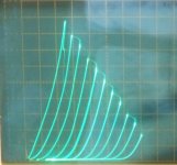
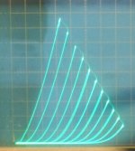
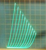
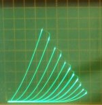
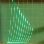
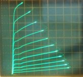
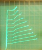
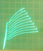
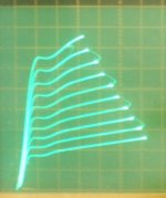
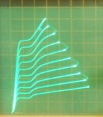
You can tell from the trioded curves how linear the grid1 is. Evenly spaced triode curves are very linear. Ones that bunch up and fall over to the right (HV) side have high 2nd harmonic and a trailing series of higher harmonics. 2nd, 3rd and 4th harmonic in SE will turn into 3rd, 5th and 7th harmonic in P-P. (less so in class A though) The bunching up is caused by the grid being too close to the cathode compared to the griid wire to wire spacing. (to get higher gm)
So high gm tubes are immediately suspect. Although frame grids CAN keep the linearity under control with high gm. But most frame grid tubes are STILL optimized for max usable gm. (so not that great) One exception is the TFH.
The other thing to check for is rounded over pentode plate curve knees or rounded curves across the board. These are caused by excessive screen grid current distortion. The rounding can remove some 2nd harmonic distortion over a limited plate voltage range, but will go badly awry at higher output levels.
Then there is variance between individual tubes caused by poor g1 g2 wire alignment (causing high g2 current),or poorly aligned (tilted wrt cathode) grid1, see the 36MC6 examples below).
Some sweep tube trioded curves attached.
12BQ6
12GE5/6JN6
6HJ5
24JE6/24LQ6
29GK6 (6BQ5)
36MC6 (good example)
36MC6 (mediocre example)
36LW6
TFH (on the $1 list at ESRC)
perfect triode (1E7G parallel trioded)
Attachments
-
 rsz_36lw6_t.jpg54.4 KB · Views: 73
 -
 rsz_36mc6m_t.jpg41.8 KB · Views: 63
 -
 rsz_36mc6s_s.jpg51.8 KB · Views: 66
 -
 rsz_29gk6_t.jpg43.3 KB · Views: 802
 -
 rsz_24je6a_24lq6_t.jpg60.1 KB · Views: 823
 -
 rsz_6hj5_t.jpg36.4 KB · Views: 822
 -
 rsz_12ge5_t.jpg55.6 KB · Views: 833
 -
 rsz_12bq6_t.jpg35.3 KB · Views: 838
 -
 Perfect_Triode.jpg6.6 KB · Views: 849
 -
 TFH_in_triode.jpg97.9 KB · Views: 100
Last edited:
Here been discussed mostly usa tubes, what are good eu/gb examples?
The amp that I made for my TV uses TV tubes
The EL36
The "modern" horizontal sweep tube operates as a constant current switch. The grid voltage is usually a square wave switching between saturation (near zero volts) and cutoff.
The only schemos where I saw that have always been solid state. The hollow state HD finals have always been driven by what looks like a sawtooth with an undershoot (see attached). This comes from Color and Black and White Television Theory and Service, but they don't say where that schemo came from, and I haven't seen one like that "in the wild", as every other hollow state HD final had some sort of protective bias. Lose the horizontal time base, and the final poofs.
From the odd heater values, this looks like the schemo of some cheap TV running a PTX-less DC supply, and they couldn't be bothered to add at least a cathode resistor!
Seems this is pretty universal for hollow state as stated from Oscilloscope Techniques:
The grid of the horizontal output tube is driven by a combination sawtooth and pulse waveform, as seen in Fig. 922
It looks the same: saw3toioth with undershoot.
The screen grid of a sweep tube is usually tied through an unbypassed resistor to a fixed B+ voltage. This sets the saturated beam current, and keeps the screen grid current to a safe value. This is why you will generally find "screen drive" curves for many horizontal sweep tubes (curves drawn with G1 at 0 volts and G2 voltage stepped).
Never seen that either. The screens have always been bypassed.
The horizontal sweep tube was never designed for linear operation, but many of them do prove to be quite linear.
I don't know how they were designed, but everything looks like they were designed to linearly amplify a sawtooth while operating like an RF amp in Class C: the grid derived bias (less the hold-down bias in case the horizontal oscillator goes out). The only reason I can see for not including any sort of audio duty is that the most linear, Class A region is well within Red Plate Territory. They also make very poor pseudotriodes and UL stages due to the low screen voltage specs. If HD finals were "just switches" I'd expect they'd be no more linear than any transistor, and definitely not like 6V6's on steroids.
Attachments
We use a Compactron 6AF11 (just one!) in the Percolator 2W guitar amp. We use National brand because they are in pretty good supply from a couple of different warehouses, and they pass our QC pretty consistently.
Here is an article published by GE in 1960 announcing their great technological breakthrough:
Compactrons: Advance In Tube Design
Here is an article published by GE in 1960 announcing their great technological breakthrough:
Compactrons: Advance In Tube Design
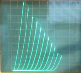
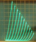
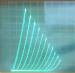
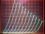
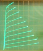
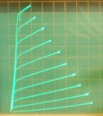
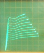
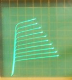
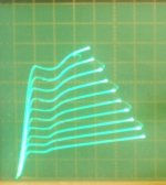
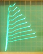
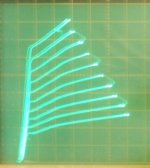
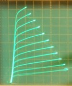
Here are some pics of g2 drive plate curves with the g1 set at 0V, -V, or +V (see below).
Scales are 50 mA/div Vert. and 50 V/div Horiz. about -7.5V steps on g2 with a positive DC bias added.
21HB5 0V on g1, +100V on g2 + steps
21HB5 -14V on g1, +200V on g2 + steps
21HB5 +8V on g1, +72V on g2 + steps
26LX6 (= 6KD6) 0V on g1, +70V on g2 + steps
26LX6 -13V on g1, +130V on g2 + steps
36MC6 (26LX6 clone by RCA) 0V on g1, +70V on g2 + steps
36MC6 -13V on g1, +130V on g2 + steps
36MC6 usual g1 stepped pentode curves
Notice (on the 21HB5 curves) that - g1 reduces the gm for grid 2 (and puts big kinks in the curves), and that + g1 increases the gm for grid2 (although not linearly). I assume this has something to do with aligned grid wires and focusing effects. (and some g1 current at low plate V with the + g1)
There is a 120 Ohm grid stopper on g2 for all the curves. Doesn't seem to have much effect when shorted out.
Attachments
-
 rsz_36mc6_p.jpg44.5 KB · Views: 99
 -
 rsz_36mc6_g2_150_13.jpg53 KB · Views: 98
 -
 rsz_36mc6_g2_70_0.jpg56.2 KB · Views: 97
 -
 rsz_26lx6_g2_130_13.jpg60.4 KB · Views: 746
 -
 rsz_26lx6_g2_70_0.jpg61.8 KB · Views: 755
 -
 rsz_21hb5_g2_p8_72.jpg55.9 KB · Views: 754
 -
 rsz_21hb5_g2_14v_200v.jpg43 KB · Views: 760
 -
 rsz_21hb5_g2_0v_100v.jpg48.7 KB · Views: 929
Last edited:
The screen drive curve set for that Danielak Screen Drive EL509 looks like a Spice model printout.
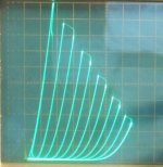
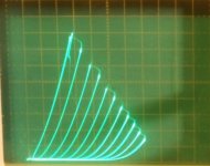
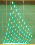
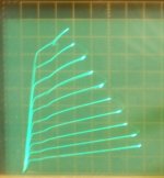
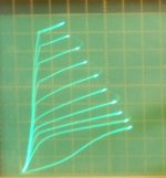
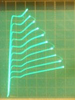
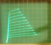
I went through and checked a bunch of Sweep tubes here using -15V on g1 as used in the Danielak design, and they all have horrible kinks in them that way. (well, 6HJ5 and 26LX6 have just flat spots) The -15V on g1 (and g2 driven) curves are shown below. (I don't have an EL509 to trace here.)
With 0V on g1, all these tubes have very nice clean beautiful g2 drive plate curves.
All are scaled 50 mA/div Vert., 50V/div Horiz. approx. 7.5 V steps on g2 with + DC bias shown in filename. (and -15V on g1)
36LW6 (RCA shown, but Sylvania was similar)
6LB6
6HJ5
35LR6
24JE6
21LG6
6CB5A
and for comparison:
a 6HJ5 with 0V on g1,
and 21HB5A with 0V on g1
One --might-- get away with a 6HJ5 or 26LX6 in that Danielak design, but anything else....pfffft.
(can not trust Spice models for g2 drive if Vg1 is not 0 ....)
Attachments
-
 rsz_6cb5a_g2_15_210.jpg47.4 KB · Views: 85
 -
 rsz_21lg6_g2_15_160.jpg53.2 KB · Views: 76
 -
 rsz_24je6_g2_160_15.jpg54.7 KB · Views: 147
 -
 rsz_35lr6_g2_15_150.jpg58.5 KB · Views: 140
 -
 rsz_6hj5_g2_15_160.jpg54.9 KB · Views: 137
 -
 rsz_6lb6_g2_15_160.jpg54.8 KB · Views: 141
 -
 rsz_36lw6_g2_15_160.jpg55.1 KB · Views: 152
 -
 rsz_6hj5_g2.jpg56.2 KB · Views: 77
 -
 rsz_21hb5_g2.jpg56.4 KB · Views: 77
Last edited:
- Home
- Amplifiers
- Tubes / Valves
- Those Magnificent Television Tubes