thanks!
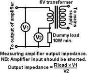
Long ago I saved this little setup to measure Output impedance, posted by MerlinB. I see that Paul substituted the 6V transformer with the driven channel - very clever") 1) doesn't require external components, and 2) one can measure at different frequencies.
1) doesn't require external components, and 2) one can measure at different frequencies.
and because DF is based on output impedance and the attached load, Rload doesn't get into the equation.
learned something new today, many thanks!
Erik
Long ago I saved this little setup to measure Output impedance, posted by MerlinB. I see that Paul substituted the 6V transformer with the driven channel - very clever
1) doesn't require external components, and 2) one can measure at different frequencies.and because DF is based on output impedance and the attached load, Rload doesn't get into the equation.
learned something new today, many thanks!
Erik
Attachments
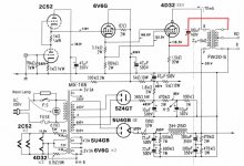
OMG! Not sure WHAT to call that.
The R divider under the 6V6 follower is not proportioned by the Mu of the 4D32, so it is mostly (effectively) driving g1, until g1 draws some current, then it mainly drives g2 on up. I have no idea what kind of transfer function that would end up doing. No global Fdbk either, but some limited CFB for g1.
One might look at the g1 drive as a current drive with that 3.3K Ohm resistor in series. Up to a point, the current drawn by g1 is determined by a grid interception ratio, so acts like a bipolar transistor with current gain Beta. As the Beta falls off at high current, the 3/2 power law of the g2 voltage drive would be picking up the slack, so some compensation range may be possible. (this kind of hybrid approach did get a brief mention some while back when Mu proportioned g2/g1 drive was discussed in some early threads)
Well, let's just say that ANY tube can be g2 driven if you can supply sufficient drive. In this case it looks like they sort of cheated (maybe quite cleverly). Maybe it works all right. Any distortion numbers available? Was this for a Bass Guitar amp?
I guess I could try that on the curve tracer for a different tube (I don't have any tubes specifically designed for positive g1). Probably requires some considerable tweaking of the R divider to get something near linear.
Zero bias tubes can also be driven as a negative bias g1 tube if the screen voltage is increased enough (well beyond ratings usually, we know how that goes around here! Maybe Tubelab has a 4D32 laying around?). All a matter of perspective what you call the tube.
Last edited:
One problem with current drive to the g1 is that the CFB will have very little effect.
And that 20 Watt 1.5K Ohm cathode resistor under the 4D32 looks pretty inefficient.
-----------------------------
Putting +600V on g2 would allow the 4D32 to run completely in negative g1 territory (if it doesn't arc over from excessive Vg2) That might make for some bad kinks in the plate curves though at low plate V. Might be a good tube to try in triode mode, but won't be able to pull plate V very low with any load current.
Last edited:
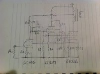
I've reworked the schematic to reduce the g1 bias. Based on what little information I can find, I decided to bias g1 slightly negative rather than take it all the way to zero. I plan to try them at -2V. The 6CM6s show too much variation between specimens at the new drive voltage. I added a divider network between them and the 12GN7a cathode followers, so I could keep the original bias conditions.
Smoking-amp, would you mind running screen driven plate curves on the 26LX6/6KD6 with g1 at -2V?
Smoking-amp, would you mind running screen driven plate curves on the 26LX6/6KD6 with g1 at -2V?
Attachments
OMG! Not sure WHAT to call that.<snip>
thanks smoking-amp, i was trying to find the japanese link where that scheme came from, no luck....
i know such scheme was discussed here before and tubelab had something similar... hope he chimes in....
Thanks for the link! I hadn't seen that thread before.
I just found the RCA reference in the TT4 manual from Pete's website. Bottom of page 239. Unfortunately, it doesn't describe the functioning of the "special triode" connection. There likely is some journal reference about it someplace. Maybe "Electron Tubes" Vol. I or II would have it.
Ah-hah! Found it:
http://n4trb.com/AmateurRadio/RCA_Ham_Tips/issues/rcahamtips0702.pdf
There might still be some journal article about it. -Lost-
Seems to have been found heuristically for best efficiency in class B with zero bias. Apparently never made it to the audio realm until recently.
Looking at those 26LX6 "special triode" curves posted above, this simply cannot be ignored!
Need to check the gain uniformity near low plate current yet. Then determine how well it performs in class aB
P-P for crossover distortion. Then look at some other Sweep tubes to see if it is generally working well with all the Sweeps.
(807 in g2 drive or "special triode" mode doesn't even make sense, too much drive voltage required. What a strange historical development. Maybe this idea came along too early, before low Vg2 Sweeps came along and got tried for audio amps. Forgotten...)
Just 55V to drive a 26LX6 pair to maybe 250 Watts output. You need that much drive for a 6L6. One thing is that secondary derived CFB will not work well with this due to g1 being largely current driven, and g2 (HV swing) being largely insensitive to CFB. Some kind of Schade or local driver feedback will be needed to lower the output Z.
Last edited:
I've been into H3 cancellation and Dual Single Ended output stage this past few months. And now this, the Holy drive. You guys rock.Holy Cow! . . . This is a major finding. . . .

re: AJT
That would be excellent. Thanks!
I can eventually add a list of linearized curves and component values for the common TV sweep tubes.
I'm going to try the linearization on a frame grid tube tomorrow, out of curiosity. Might as well have a "wire with incredible gain" too!
That would be excellent. Thanks!
I can eventually add a list of linearized curves and component values for the common TV sweep tubes.
I'm going to try the linearization on a frame grid tube tomorrow, out of curiosity. Might as well have a "wire with incredible gain" too!
Last edited:
- Status
- This old topic is closed. If you want to reopen this topic, contact a moderator using the "Report Post" button.
- Home
- Amplifiers
- Tubes / Valves
- Screen driven 6KD6 SE