
Humm the bass, Saluti tubeheads
It has been a long read/scan through 33 pages ... and during the read I recognized many problems / issues and had several "AHA -ERLEBNISSE".
This thread has become a BOYUU A9/A10 WIKI like thingy except for one thing: it is not organized nor compact. I would volunteer to wrap up: posting a schematic with "definite" wiring/components but I can't. There are several issues and I am not sure what is the last word on matters. I did some readings with voltmeter, but since my A9 hums VERY LOUD something is wrong which may influence readings. Summary of the issues / upgrades:
- ultra linear versus triode mode: switch / wiring required versus UL only versus triode mode only. Maybe a schematic with "optional lines/switch" is possible.
- better ON/OFF switch with anti arc condensor required? Several people report to "upgrade" but why? is the switch unsave or bad? And better: dual line switch with 2 condensors may really save a day?
- ON/OFF indicator light, to me this is required for safety as well as energy and tube saver, so should be in the schematic. I would have changed my tubes in my Fender Twin for sure several times if it would not have been switched off because of the bright indicator light. I have that thing 40 years today and changed the tubes in 1986 lastly. And I do play on it, ask my wife, maybe better not")
- input resistor that need to block interference of some kind? where and how to insert best? Best option: 10K metal film 1/4 watt at 6n9pj tube input pens?
- the Boyuu ships R103/203 with 100k 2w but schematic shows r = 75k. Change value or change resistor. On my schematic NobSound changed by handwriting (!) the value to 100k ... My belief is that the B2 voltage is too high if the amp is hooked to EU supply (240VAC). When switched on cold B2 goes to 422V and drops quickly to 358V and ends at 223V . (the same voltages are on at the pens on the tube). The 6n9pj is rated MAX 275vac ... Is 223V too low and should the resistor actually be 75k?
- Same as previous for R105/205, was 470k is now 330k. Again: change schematic or change resistor?
- several people replace the ELCO's on the spot. Why and what is the guideline. Boyuu is shipped with many different setups. My C302 is in schematic 150uF/450V but it had a 180uF/450V in the bag labelled NICHICON. The matter to settle is: what elco's by "brand" and capacity/voltage are at minimum required.
- several people replace the tubes's on the spot. Why and what is the guideline? Boyuu is shipped with apparently a decent el34 end tube but a moderate 6n9pj preamp?. Matters to settle:
* how 'bad' is the Chinese basic setup;
* what tube would improve on what aspect (types: ecc86 etc.) against what cost, is there a "best buy"?
* APPARENT 6n9pj replacement options under study: 6SL7 6N9 5691 6SU7 33S29B 6113 6188 CV569 VT229 ECC35, what to add, what to remove, which is best ...
* Who is playing "out of the box" and is perfectly happy?
When the hurly burly has been done it boils down to a schematic.
And for sure there are many options which may settle by just adding things in "options". For instance, in the schematic "V1 6N9PJ" would change to, for example, "V1 Tube 1" with a bottomline: Tube 1 = Phillips ECC86 / Coconut ABC123 / etcetera.
To keep things going I shall put the schematic into the computer and post it here asap but not this last Formula 1 weekend ... GO MAX!.
Happy soldering,
MakW
It has been a long read/scan through 33 pages ... and during the read I recognized many problems / issues and had several "AHA -ERLEBNISSE".
This thread has become a BOYUU A9/A10 WIKI like thingy except for one thing: it is not organized nor compact. I would volunteer to wrap up: posting a schematic with "definite" wiring/components but I can't. There are several issues and I am not sure what is the last word on matters. I did some readings with voltmeter, but since my A9 hums VERY LOUD something is wrong which may influence readings. Summary of the issues / upgrades:
- ultra linear versus triode mode: switch / wiring required versus UL only versus triode mode only. Maybe a schematic with "optional lines/switch" is possible.
- better ON/OFF switch with anti arc condensor required? Several people report to "upgrade" but why? is the switch unsave or bad? And better: dual line switch with 2 condensors may really save a day?
- ON/OFF indicator light, to me this is required for safety as well as energy and tube saver, so should be in the schematic. I would have changed my tubes in my Fender Twin for sure several times if it would not have been switched off because of the bright indicator light. I have that thing 40 years today and changed the tubes in 1986 lastly. And I do play on it, ask my wife, maybe better not
- input resistor that need to block interference of some kind? where and how to insert best? Best option: 10K metal film 1/4 watt at 6n9pj tube input pens?
- the Boyuu ships R103/203 with 100k 2w but schematic shows r = 75k. Change value or change resistor. On my schematic NobSound changed by handwriting (!) the value to 100k ... My belief is that the B2 voltage is too high if the amp is hooked to EU supply (240VAC). When switched on cold B2 goes to 422V and drops quickly to 358V and ends at 223V . (the same voltages are on at the pens on the tube). The 6n9pj is rated MAX 275vac ... Is 223V too low and should the resistor actually be 75k?
- Same as previous for R105/205, was 470k is now 330k. Again: change schematic or change resistor?
- several people replace the ELCO's on the spot. Why and what is the guideline. Boyuu is shipped with many different setups. My C302 is in schematic 150uF/450V but it had a 180uF/450V in the bag labelled NICHICON. The matter to settle is: what elco's by "brand" and capacity/voltage are at minimum required.
- several people replace the tubes's on the spot. Why and what is the guideline? Boyuu is shipped with apparently a decent el34 end tube but a moderate 6n9pj preamp?. Matters to settle:
* how 'bad' is the Chinese basic setup;
* what tube would improve on what aspect (types: ecc86 etc.) against what cost, is there a "best buy"?
* APPARENT 6n9pj replacement options under study: 6SL7 6N9 5691 6SU7 33S29B 6113 6188 CV569 VT229 ECC35, what to add, what to remove, which is best ...
* Who is playing "out of the box" and is perfectly happy?
When the hurly burly has been done it boils down to a schematic.
And for sure there are many options which may settle by just adding things in "options". For instance, in the schematic "V1 6N9PJ" would change to, for example, "V1 Tube 1" with a bottomline: Tube 1 = Phillips ECC86 / Coconut ABC123 / etcetera.
To keep things going I shall put the schematic into the computer and post it here asap but not this last Formula 1 weekend ... GO MAX!.
Happy soldering,
MakW
Last edited:
2nd lamp
Saluut!, In finishing my first build tube amp ever, A9, and to fight the HUMM I soldered the 10kOhm input resistor on one channel and left the 2nd channel without tubes. It brings down HUMM at least 50%. Also: without the resistor turning the volume know did not make any change in the HUM. With the resistor it does: Volume @ minimum the channel HUMMS and volume @ max hum gets low, almost acceptable!. In addition with the 2nd set tubes, speaker and resistor installed the noise cuts again in half. It is still hearable.
The input resistors are a "must have" but I wonder: since the triodes in the 6n9p work in parallel, why not splitting the signal with 2 resistors to input pins individually.
First chunk of drawing is ready and I put it up.
In this 0.2 version one 240V lamp is used to indicate "power ready", a second lamp could be used to indicate "ON", but where. To warn for high voltage, on the high voltage?
Have a nice weekend, MakW
I cannot post the image as attachment?
Uploading is limited somewhere to 200.000. Bytes?
The image is scaled down much, JUST readable and even then I get this message:
"The text that you have entered is too long (78364 characters). Please shorten it to 30000 characters long."
Please can anyone advise how to upload.
cheers,
Marcel
In red: changes/problems. The picture is redrawn from 'original' and NobSound instructions, plus 1 upgrade: input resistor.
Help please
Hello everyone,
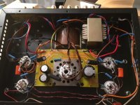
Having thoroughly read this topic, and having completed my own A9 kit, I’ve just hit a dead end.
On powering the amp up, I get a huge hissing noise coming from the OPTs, roughly 15 seconds after power up. I get about 10V at the 8 ohms output !
I have desperately tried to identify any possible mistake I could have made, so far without success.
Here’s a picture of the beast.
Hello everyone,
Having thoroughly read this topic, and having completed my own A9 kit, I’ve just hit a dead end.
On powering the amp up, I get a huge hissing noise coming from the OPTs, roughly 15 seconds after power up. I get about 10V at the 8 ohms output !
I have desperately tried to identify any possible mistake I could have made, so far without success.
Here’s a picture of the beast.
Attachments
Have you grounded the '0V' part of the OPT secondary i.e not left it floating.
How are you measuring the 10 volts you see. Is it on a scope or on a meter, and if a meter are you on DC or AC ?
There should be no DC present. AC (and the noise you hear) suggests instability and oscillation somewhere.
How are you measuring the 10 volts you see. Is it on a scope or on a meter, and if a meter are you on DC or AC ?
There should be no DC present. AC (and the noise you hear) suggests instability and oscillation somewhere.
Hello,
Thanks for the replies. I have identified some weird relationship with the hiss and the line entrance from the potentiometer. I have now reworked the grounding of the faceplate as well as the 0V from the OPTs as suggested. It works fine but I have a very present 50hz hum in the speakers now.
Ideas ?
Hum can be difficult to trace and eradicate. Pure 50Hz hum (a pure deep tone) suggests it could be being induced into wiring, or perhaps a ground loop. If it is a harsher buzz then it is more power supply related.
Does it hum with the inputs shorted ? and does the hum alter with volume ?
Does it hum with the inputs shorted ? and does the hum alter with volume ?
The hum disappears when I ground the input pin on the preamp tube.
I have tried disconnecting the potentiometer from it, without any change, which suggests the hum would appear somewhere around the valve.
It is equally present on both channels.
At the moment I am measuring 630mV at the speaker connector, with no source signal.
I have tried disconnecting the potentiometer from it, without any change, which suggests the hum would appear somewhere around the valve.
It is equally present on both channels.
At the moment I am measuring 630mV at the speaker connector, with no source signal.
Nice to hear your tube amp works. 50Hz Hum is much debated in de 310 long tread...
Does the hum change when you change volume?
Please read / search for suppressor resistor.
The schematic by DMAXY of post #225 shows mods to kill hum, results are very positive.
www.diyaudio.com/forums/attachments...el34-a9-tube-amp-a9-schematic-mods-rev1-2-pdf
Get back here if you want, I can do some measurements if you need.
Marcel
I wanted to thank all the contributors of this thread, I finished this amp using a lot of advices ! There are still some problems of hum, a kind of distortion in the high medium (specialy with high pitched voices, piano, natural strings). But the sound is not bad and I don't have made all the possible improvement.
I bought this kit to have a base of experimentation in SE, but for this price the sound is not bad. I have only changed the signal capacitors for russian PIO models, potentiometer for an ALPS and the cheap rear selector.
After some breaking time I would experiment the changes provided by DMAXY.
I bought this kit to have a base of experimentation in SE, but for this price the sound is not bad. I have only changed the signal capacitors for russian PIO models, potentiometer for an ALPS and the cheap rear selector.
After some breaking time I would experiment the changes provided by DMAXY.
DMAXY was drawn by hand if I rememeber and schematic has used the 100K resistor for R103/203 as in the KIT, but does NOT have a surpressor R. All other schematics (GIDO, Geekstuff and others) have a 75K resistor for R103. Does this effect the schematics /function at all? Can I change R103 in Geekstuff schematic?
Hum/50Hz noise: Triode Dick (contemporary Dutch tube amp designer) takes a bit hum out by upgrading the selector in ALL designs: "Een hele hete tip is: schakel niet alleen de signaalweg, maar ook de afscherming."
My experience: take the time to burn in the tubes seriously. I can hear more high comming in and less fluttery (if that is a word) while deep bass straightens out @around 100 hours music, going on to present @150 hours. The only stable sound aspect is the 50hz hum in the beginning
This implies that if you start to change things early (<100 hours) it will be very difficult to know (hear! or measure)) what changes do with the music and therefor obscuring your optimal path to the best sound experience.
The 7T law: Tuning Tubes To The Top Takes Time.
Marcel
PS. Triode Dick sais: use a selector with 4 poles and thus cut schielding (L+R) as well as signal (L+R) to prevent noise from other apparatus to get in the amp via shielding. Makes sense to me.
Hi All
I’m new on here, an also new on tube amps. Searching on the Internet for a small beginner tube amps, I stomped over this thread. That was very interesting to read the whole thread (32 pages). Then I bought a pre-built Boyuu A9 EL34 from a stock in Germany. First thing I do, was open the tube amp, and check all connections and the value of all components. Insetting the tubes and slowly get power on with my vario-transformer (Nordmende RT 397/1). No smoke or explosion, just the warm glow from the tubes, and turning the volume up, music flows out of the speakers.
The schematic (originally posted by Celsius) is identical to my Boyuu A9 except from some value of components. My tube amp is build for AC240V. Here in Denmark the average voltage is AC230V. I have changed the values on the schematic, so you can see the values for my AC240V version. Resistor R107 and R108 are one resistor 500 ohm 6 watt. And the same for R207 and R208.

I have measured some voltages at AC230V line in:
AC305V on the rectifier pin 4 and 6 according to ground (With AC240V line in, there is AC315V, as shown in the schematic).
DC320V on B1 (B+ on the PCB), and DC296V on B2.
DC310V on pin 3 (anode on tube EL34).
DC315V on pin 4 (grid on tube EL34).
DC22V on pin 8 (catode on EL34).
DC146V on pin 2 and 5 (anode on tube 6N9P).
DC1.5V on pin 3 and 6 (catode on 6N9P)
And here some photos:


And a Merry Christmas to all of you.
I’m new on here, an also new on tube amps. Searching on the Internet for a small beginner tube amps, I stomped over this thread. That was very interesting to read the whole thread (32 pages). Then I bought a pre-built Boyuu A9 EL34 from a stock in Germany. First thing I do, was open the tube amp, and check all connections and the value of all components. Insetting the tubes and slowly get power on with my vario-transformer (Nordmende RT 397/1). No smoke or explosion, just the warm glow from the tubes, and turning the volume up, music flows out of the speakers.
The schematic (originally posted by Celsius) is identical to my Boyuu A9 except from some value of components. My tube amp is build for AC240V. Here in Denmark the average voltage is AC230V. I have changed the values on the schematic, so you can see the values for my AC240V version. Resistor R107 and R108 are one resistor 500 ohm 6 watt. And the same for R207 and R208.
I have measured some voltages at AC230V line in:
AC305V on the rectifier pin 4 and 6 according to ground (With AC240V line in, there is AC315V, as shown in the schematic).
DC320V on B1 (B+ on the PCB), and DC296V on B2.
DC310V on pin 3 (anode on tube EL34).
DC315V on pin 4 (grid on tube EL34).
DC22V on pin 8 (catode on EL34).
DC146V on pin 2 and 5 (anode on tube 6N9P).
DC1.5V on pin 3 and 6 (catode on 6N9P)
And here some photos:
And a Merry Christmas to all of you.
Last edited:
Just built the A9 and have started checking DC voltages et with rectifier valve inserted and no load.
I have the version with r9 (39R) connecting rectifier pin 8 to choke and smoothing capacitors.
Upon switch on this resistor started to overheat.
I connected the resistor to pin 2 and got DC voltages.
Anyone know why this would happen?
Definatly shows pin 8 on the diagram.
I have the version with r9 (39R) connecting rectifier pin 8 to choke and smoothing capacitors.
Upon switch on this resistor started to overheat.
I connected the resistor to pin 2 and got DC voltages.
Anyone know why this would happen?
Definatly shows pin 8 on the diagram.
- Home
- Amplifiers
- Tubes / Valves
- Boyuu EL34 A9 Tube Amp