Thank you very much for your order.
Sorry for the belated response. I was traveling. You can get rid of the LC filters in the supply if you wish. The Maida Regulator will provide plenty of regulation, so you don't need all the filtering. I'd leave C11 and C12 and hook the regulator to C12.
Tom
I will rewire the chokes in parallel and drop the common mode wiring. That
will drop the series resistance to 9 ohm/choke (1+2mH) Most likely I will drop
C11 as well. 50uf at the output of the regulator wouldn't be optimal anyway (if
I have read the thread correctly). That will also give me space enough to
make it fit inside the amp. The ribbon drivers are quite delicate so I want to
keep a decent level of rejection if the regulator for some reason would
malfunction. Not sure what would happend if it did, depends on how of cource
but anyway......Changing to the 390V tap and lowering the dc resistance over
the chokes will give me 20V higher voltage than I have today. Just changing
taps gives 13V. Dropping the chokes all together would only give me 3V and
since the amp is class A a bit of resistance shouldn't be a problem.
Best regards. Bengt
Putting chokes in parallel wouldn't be my first choice. I'd put them in series. If that leads to too much voltage drop, consider taking one of the chokes out. You can leave it on the chassis, just short it out.
It also turns out that I was reading the schematic wrong. Normal schematic convention is that signal flows left to right and in a power supply, the power flow is the signal. Your schematic threw me off for a bit and caused me to misread the it. The fact that I was winding down after a 12-hour drive when I looked at it could have been a factor as well...") Anyway... Sorry about that.
Anyway... Sorry about that.
I would move the 4H inductor up the chain. So GZ30 - 30 uF - 4 H - 100 uF - 21st Century Maida - Amp. If the GZ30 can handle it, consider putting the remaining caps in parallel with the 100 uF before the regulator. You don't need any significant amount of cap after the regulator. I normally put 10 uF at the power input to the amp. That's mostly to minimize the impact of the supply wiring. The regulator doesn't care.
Tom
It also turns out that I was reading the schematic wrong. Normal schematic convention is that signal flows left to right and in a power supply, the power flow is the signal. Your schematic threw me off for a bit and caused me to misread the it. The fact that I was winding down after a 12-hour drive when I looked at it could have been a factor as well...
Anyway... Sorry about that.I would move the 4H inductor up the chain. So GZ30 - 30 uF - 4 H - 100 uF - 21st Century Maida - Amp. If the GZ30 can handle it, consider putting the remaining caps in parallel with the 100 uF before the regulator. You don't need any significant amount of cap after the regulator. I normally put 10 uF at the power input to the amp. That's mostly to minimize the impact of the supply wiring. The regulator doesn't care.
Tom
Sorry if I have been unclear
Chokes still in series
http://www.dahlbergaudiodesign.se/kr_300b_xls_ver2.pdf
The chokes in the earlier chematic are two Lundhal dual winding chokes
connected as common mode chokes. You have the opportunity to
connect the windings in parallel as well, that's what I ment.
http://www2.lundahl.se/wp-content/uploads/datasheets/1638.pdf
Edit: Missed the ground connection of the regulator.
Last edited:
2 mH into 100 uF --> fc = 356 Hz.
1 mH into 100 uF --> fc = 503 Hz.
I.e. you won't get any filtering at 100 Hz where it matters. You will get some filtering of the higher order harmonics of the mains frequency, though.
I'd take the 1 mH out and put C12 in parallel with C13 after the 2 mH inductor. That'll give you 2 mH into 200 uF --> fc = 252 Hz. You may want to run a sim in PSUD II to make sure you're not pushing the limits on the peak current of the rectifier tubes.
Tom
2 mH into 100 uF --> fc = 356 Hz.
1 mH into 100 uF --> fc = 503 Hz.
I.e. you won't get any filtering at 100 Hz where it matters. You will get some filtering of the higher order harmonics of the mains frequency, though.
I'd take the 1 mH out and put C12 in parallel with C13 after the 2 mH inductor. That'll give you 2 mH into 200 uF --> fc = 252 Hz. You may want to run a sim in PSUD II to make sure you're not pushing the limits on the peak current of the rectifier tubes.
Tom
Did I write mH
Apparently  I really have to get better sleep at night .
 It should be ok now.Thanks for pointing it out though
There will most likely be a rev3 before this is done as well so thanks for the tips.
I'm pushing the rectifier a bit I know, it seems to be ok anyway. Has been in use almost every day for two years so......
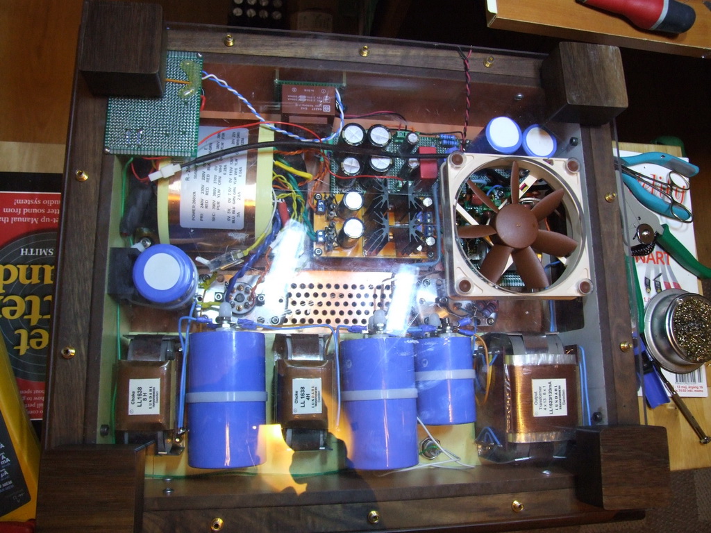
I have recived the pcb's and components but I'm not sure about how much
cooling I will need. There is a part of the amps top that's 410x70x1mm copper
sheat metal that I'm hoping would work as a sufficient cooler. As you can see
there is an evacuating fan keeping the thing cool already, that will help as well.
Am I being to optimistic ?
I'm dropping the voltage 15-20v and the amp draws 100-110mA.
Unregulated B+ 480v.
I just got my board all built up and am getting ready to install it. I bought the recommended thermal pad (BER178-ND) but I also saw this aluminum oxide ceramic thermal pad that, if I am reading the specs correctly, seems to have much better thermal performance (4180G-ND). Is there any reason I shouldn't go with the aluminum oxide pad?
Thermal resistance for the Sil-Pad is .61 degree C/W. The Aluminum oxide is 18.01W/mdegree C @ 25 degrees C.
This is the B+ supply for a quad of KT88s in a push-pull amp and the pass device will be dissipating 20+ Watts.
Thermal resistance for the Sil-Pad is .61 degree C/W. The Aluminum oxide is 18.01W/mdegree C @ 25 degrees C.
This is the B+ supply for a quad of KT88s in a push-pull amp and the pass device will be dissipating 20+ Watts.
The aluminum oxide pads have 11x higher thermal conductivity than the SilPad 900, but they're also 7.8x thicker, so the benefit isn't as great as you'd think from just comparing the conductivities. It would be handy if Aavid published the thermal resistance data when used with a TO-220 or TO-247 package, so an apples-to-apples comparison could be done. Sadly, they don't.
Aside from cost, I don't see any reason to not use the aluminum oxide pads. At QTY = 1, the extra $0.30 can probably fit within the build budget...
Personally, I have yet to try the aluminum oxide pads. I'm pretty happy with SilPad. The 1500ST is awesome stuff.
Tom
Aside from cost, I don't see any reason to not use the aluminum oxide pads. At QTY = 1, the extra $0.30 can probably fit within the build budget...
Personally, I have yet to try the aluminum oxide pads. I'm pretty happy with SilPad. The 1500ST is awesome stuff.
Tom
I have an IR thermometer so it should be easy to do the measurements. The big thing I'm lacking right now is time but I'll get there by this weekend or next. I'll describe my methodology in detail.
I want to know if it is better and by how much as well. I don't mind spending an extra 30 cents to get even a small improvement in thermal performance but I do want to be sure that it is in fact an improvement. And the data sheets give me just enough information to raise a bunch of questions. It's not my area of expertise.
I want to know if it is better and by how much as well. I don't mind spending an extra 30 cents to get even a small improvement in thermal performance but I do want to be sure that it is in fact an improvement. And the data sheets give me just enough information to raise a bunch of questions. It's not my area of expertise.
The regulators are in place and seem to be working as expected
I settled for 435v B+ to get a bit more ac variation security.
I got a bit lazy and did not replace the capasitor after the regulator.
It's now 50uf and it seems to be working, could this for some reason
be a problem ?
I have the abillity to replace the 50uf mkp with a 630v/10uf russian pio.
First impressions on SQ is positive
http://www.dahlbergaudiodesign.se/kr_300b_xls_rev3.pdf
the STW12NK95Z seems to be on its way out at Mouser , what product would you recommend using instead of the STW12NK95Z
For now, Digikey shows them in stock, so I suggest shopping there.
They made the STW12... a non-stock item a few years ago and their stock has slowly depleted. I wouldn't worry too much about availability in the short term. I also have the better part of a tube of them, so at least until I run out, you can buy them from me as well.The STW11NK95Z looks like a good candidate for a replacement and is in stock at Mouser (and Digikey).
Tom
***Correction; part STW11NK95Z is a nonexistent part
a proper substitute for STW12NK95Z => STW13N95K3 <=
this part is available at digikey, farnell, mouser
NB:
parts; STW11NK90Z; STW12NK95Z are OLDER parts from 2006 with SuperMESH(1)
The STW13N95K3 is more recent with SuperMESH(3)
---Tom, can you add this substitute on your website please---
a proper substitute for STW12NK95Z => STW13N95K3 <=
this part is available at digikey, farnell, mouser
NB:
parts; STW11NK90Z; STW12NK95Z are OLDER parts from 2006 with SuperMESH(1)
The STW13N95K3 is more recent with SuperMESH(3)
---Tom, can you add this substitute on your website please---
Last edited:
***Correction; part STW11NK95Z is a nonexistent part
My finger may have slipped. The part number is STW11NK90Z. Digikey has them: STW11NK90Z STMicroelectronics | 497-6198-5-ND | DigiKey
a proper substitute for STW12NK95Z => STW13N95K3 <=
Judging from the SOA curves, the STW13N95K3 is not as rugged as the STW12NK95Z. The STW13... may have trouble with start-up into a capacitive load if used in the Maida Regulator. I've seen parts explode under those conditions.
Tom, can you add this substitute on your website please---
I would prefer to try it out in the lab before making a recommendation. As long as the STW12NK95Z is still available from Digikey and Mouser, I don't see any issue here. Mouser has 181 of them in stock. Digikey is down to 64. I forget how many I have. Probably ten.
I'm reasonably confident in the STW11NK90Z as it's even more rugged than the STW12NK95Z, judging by the SOA curves, and its internal capacitances are similar to those of the STW12NK95Z. Before changing the BOM, I do prefer trying it out in the lab, though.
Tom
Last edited:
Negative Maida Regulator
Team,
I asked Tom about a negative maida reg
He kindly advised "I don’t have a negative Maida Regulator, but if you run two Maida Regulators on completely separate transformer windings, it should be possible to connect them in series. I haven’t tried that personally, but it should be possible. I’d set it up in LTspice before building it, though."
The positive and negative high voltage regs would be for a valve amp that requires both voltages.
Is there anyone out there who could test Tom's suggested set up in Spice?
best regards
tim
- Home
- Vendor's Bazaar
- 21st Century Maida Regulator