An externally hosted image should be here but it was not working when we last tested it.
Watch out for the power dissipation in the pot. I can easily see that go up in smoke...
Tom
No guts no glory ")
I've built tube amplifiers before, but at lower voltages. Successfully adapting your designs to fit my strange needs is a bit to difficult. But that's why you're a electronic engineer and i'm a mechanical engineer.
So implementing a series regulator tube as cascode is a great idea but I don't know exactly what changes are needed to make it work.
No guts no glory
Yeah... Just be careful.
So implementing a series regulator tube as cascode is a great idea but I don't know exactly what changes are needed to make it work.
I think it sounds like a really cool project. I'd love to help, but unfortunately, I don't have the time right now. However, I'm sure you'll find help if you start a new thread on the topic. I'll be more than happy to help out there to the extent time allows.
Tom
Yeah... Just be careful.
I think it sounds like a really cool project. I'd love to help, but unfortunately, I don't have the time right now. However, I'm sure you'll find help if you start a new thread on the topic. I'll be more than happy to help out there to the extent time allows.
Tom
Thanks, I'll do that.
Right now I'm messing around in LTspice(mosfet cascode works great) and doing a bit more research after that I'll start a new thread.
Last edited:
Tom, as I recall, you reported an excellent PSRR - something like 20uV out of 20V ripple. Do you have a graph of output impedance vs. frequency?
Yes I do. See Post #46. Here's the plot:
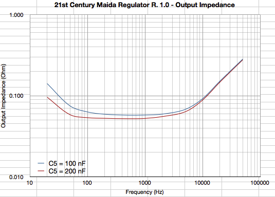
The current BOM has C5 = 220 nF. 21st Century Maida Regulator Rev. 2.0 likely has lower output impedance at higher frequencies as the layout has been optimized for that. I've yet to take the measurement to confirm, though.
Tom
Tom, I am currently building a similar circuit based on your 21st Century Maida Regulator.
Have you ever come across this behaviour where the output voltage rise up to the set voltage, then instantly drop to around zero?. All the voltage is then appeared across the power mosfet? I think I might have cooked the LT3080.
Have you ever come across this behaviour where the output voltage rise up to the set voltage, then instantly drop to around zero?. All the voltage is then appeared across the power mosfet? I think I might have cooked the LT3080.
Tom, I am currently building a similar circuit based on your 21st Century Maida Regulator.
Have you ever come across this behaviour where the output voltage rise up to the set voltage, then instantly drop to around zero?. All the voltage is then appeared across the power mosfet? I think I might have cooked the LT3080.
Solved it, turn out one of the zener diode is defected, thus causing a short.
Glad you got it working. Do I get credit for helping?
Was it D2 that had gotten cranky?
Tom
In my case, both D2 and D4 went bad. My guess would be that because I over temperature the Zener while transferring them to a new PCB. It was working fine on the previous board.
Atleast, now I know that, if you get funny behaviour around the set voltage, it must be one of this Zener diode.
Last edited:
Hello Tom and thank you for all the effort !
I have a problem with the board i bought , it works fine with 400vdc input and 260vdc output, i can move the trimmer from 230vdc to 260vdc, that cool.
I have recently bought a new power transformer, with a supply output voltage of 556vdc , i can not get any movement from the trimmer pot anymore with this input voltage , i connect a decade resistor box for R9 to reduce the voltage that works but still no movement in the trimmer pot, what i'am i doing wrong.
The 21st Century Maida Regulator v1.0 still works , with a 400vdc input, so it is not blown up,so i have come to you to seek some advice on how to proceed on this matter.
cheers
skal
Hmmm.... So you have a regulator that worked on Supply #1 (400 V DC). You moved it to Supply #2 (556 V) and now the regulator provides about 260 V out but can't be adjusted?
What happens if you move the regulator back to Supply #1?
If tweaking the pot results in no change in the output voltage, I'd say either the pot is toast or R6 has gotten cranky. Either is pretty unlikely, but check the solder joints.
Tom
What happens if you move the regulator back to Supply #1?
If tweaking the pot results in no change in the output voltage, I'd say either the pot is toast or R6 has gotten cranky. Either is pretty unlikely, but check the solder joints.
Tom
Hmmm.... So you have a regulator that worked on Supply #1 (400 V DC).
Tom
yes
What happens if you move the regulator back to Supply #1?
Tom
reg works fine
#2 (556 V) and now the regulator provides about 260 V out but can't be adjusted?
Tom
No provide 310vdc on output no pot movement R9 120k &R3 15 ohms
regards
skal
Last edited:

No provide 310vdc on output no pot movement R9 120k &R3 15 ohms
With R9 = 120 kΩ you should get Vout = 240 V at the center of the pot's travel. The adjustment range is about ±10 % for Rev. 2.0 and more like ±5-6 % for Rev. 1.0.
Note, however, that the input voltage must be 15 V above the output voltage at all times (including during the valleys of the ripple voltage).
If you have no adjustment on the pot, there are three possibilities for failure:
1) Pot (R4) failed.
2) R6 failed.
3) Vin < (Vout + 15).
If you hook a DMM between the center pin of the pot and the output voltage, you should see a relatively small voltage (0-1 V for Rev. 1.0 and about 10x that for Rev 2.0). This voltage should change as you turn the pot. If it doesn't, R4 and R6 are the suspects.
Be careful when you take this measurement. I suggest soldering a little piece of component lead or solid core wire to the test points and clipping the DMM leads to it. That way you don't have to hold the probe. High voltages are involved and a probe slip can result in some rather spectacular fireworks.
If the regulator works fine on the previous supply, but doesn't work on the new supply, I'd suspect that the ripple voltage on the new supply is too high. You may want to measure the input voltage of the Maida Regulator with it connected to the new supply to make sure condition 3) above isn't violated.
I suppose, it's also possible that the rather extreme difference between the input and output voltages could cause too much current to flow through zener D2. That could throw things off balance as well. This is especially true for Rev. 1.0. What happens if you attach a load of a few mA to the supply?
Tom
Last edited:
Excessive voltage drop across R3 will also cause lack of regulation. You shouldn't have more than a few volt (2-3 V) across R3 at the peak output current.
My money is on excessive current through D2, though. If adding a few mA of load current on the output (so hooking a 270 kΩ resistor from Vout to GND) solves the issue, the current through D2 is the cause.
Tom
My money is on excessive current through D2, though. If adding a few mA of load current on the output (so hooking a 270 kΩ resistor from Vout to GND) solves the issue, the current through D2 is the cause.
Tom
Last edited:
Excessive voltage drop across R3 will also cause lack of regulation. You shouldn't have more than a few volt (2-3 V) across R3 at the peak output current.
My money is on excessive current through D2, though. If adding a few mA of load current on the output (so hooking a 270 kΩ resistor from Vout to GND) solves the issue, the current through D2 is the cause.
Tom
Ok Tom , will have a look at your suggestion and get back to you
cheers
I've been searching for something like this The first thougth is to put your
regulator between C11 and C12 and to shift the 380v ac tap to the the 390v tap, the amp is already built.
That would give me (at least) the necessary 15 v aquired for regulation to the 445V in the schematic. Any comments ?
http://www.dahlbergaudiodesign.se/kr_300bxls.pdf
The first thougth is to put your regulator between C11 and C12 and to shift the 380v ac tap to the the 390v tap, the amp is already built.
That would give me (at least) the necessary 15 v aquired for regulation to the 445V in the schematic. Any comments ?
http://www.dahlbergaudiodesign.se/kr_300bxls.pdf
Thank you very much for your order.
Sorry for the belated response. I was traveling. You can get rid of the LC filters in the supply if you wish. The Maida Regulator will provide plenty of regulation, so you don't need all the filtering. I'd leave C11 and C12 and hook the regulator to C12.
Tom
Sorry for the belated response. I was traveling. You can get rid of the LC filters in the supply if you wish. The Maida Regulator will provide plenty of regulation, so you don't need all the filtering. I'd leave C11 and C12 and hook the regulator to C12.
Tom
- Home
- Vendor's Bazaar
- 21st Century Maida Regulator