Hi Tom
Thanks for reply.
You spend a lot of effort for the 21st Maida so it´s absolute resonable to earn some money with this project.
So for me this means start to fill up my piggybank to get the latest PCB and the rest of information.
Again: thanks a lot for your work and sharing all the information with us.
Best regards
Karsten
Thanks for reply.
You spend a lot of effort for the 21st Maida so it´s absolute resonable to earn some money with this project.
So for me this means start to fill up my piggybank
to get the latest PCB and the rest of information.Again: thanks a lot for your work and sharing all the information with us.
Best regards
Karsten
The times I've had the MOSFET fail (during development, never during actual use) it has failed open. In one case, it exploded. If it was to fail short, it'll probably blow the LT3080 off the board. If it didn't, you're right that you'd get the full input voltage present at the output.
If you want to guard against this, I suggest looking into crowbar circuits. Basically, you need to trigger an SCR that's beefy enough to short out the supply until the mains fuse blows. It could be a lot of fun to design such a circuit. Wear safety glasses...
Tom
If you want to guard against this, I suggest looking into crowbar circuits. Basically, you need to trigger an SCR that's beefy enough to short out the supply until the mains fuse blows. It could be a lot of fun to design such a circuit. Wear safety glasses...
Tom
I'm doing some research on your design and I plan on applying a similar configuration to a project I am working on. Have you seen the LT3080 design published in the new Art Of Electronics text? It is very similar to yours and employs a current regulator instead of R1 which doesn't seem like a bad idea to me. Do you have any thoughts about this? A brief discussion about the Art of Electronics configuration can be found here: http://www.diyaudio.com/forums/power-supplies/290753-lt3080-high-voltage-floating-regulator.html Also, do you think it is possible to substitute R9 with a current mirror controlled by a DAC? -Ohmicide
I haven't seen the new AOE, so thank you for bringing it to my attention.
A current source for R1 is not a bad idea, if you can make its output impedance high enough. I doubt you'll beat the 1 MΩ I use, so it may actually hurt the line rejection.
R9 in my design has a constant 2 mA current flowing in it. If you wanted the output voltage to be adjustable by a DAC, you'd have to shunt some of this current away from R9, i.e. put a current output DAC in parallel with R9. Your DAC will need to be able to survive the full output voltage, so you're probably looking at a current mirror like you mentioned.
Tom
I haven't seen the new AOE, so thank you for bringing it to my attention.
A current source for R1 is not a bad idea, if you can make its output impedance high enough. I doubt you'll beat the 1 MΩ I use, so it may actually hurt the line rejection.
R9 in my design has a constant 2 mA current flowing in it. If you wanted the output voltage to be adjustable by a DAC, you'd have to shunt some of this current away from R9, i.e. put a current output DAC in parallel with R9. Your DAC will need to be able to survive the full output voltage, so you're probably looking at a current mirror like you mentioned.
Tom
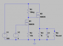
A depletion mosfet cascode current source with will have Zout in the tens of megOhms.
A simpler method for a DAC adjustable HV supply in bare bones -- imagine V2 as a DAC. For a regulated supply you can use an error amp in the control loop. One of my Heath Supplies had the tubes removed and this circuit substituted -- for an article in AX in 2003.
Attachments
A depletion mosfet cascode current source with will have Zout in the tens of megOhms.
A simpler method for a DAC adjustable HV supply in bare bones -- imagine V2 as a DAC. For a regulated supply you can use an error amp in the control loop. One of my Heath Supplies had the tubes removed and this circuit substituted -- for an article in AX in 2003.
It's not going to work Jackinnj.. where am I going to get a precision HV rail with zero ripple?
It's not going to work Jackinnj.. where am I going to get a precision HV rail with zero ripple?
The 2 DMOS current source was described by Walt Jung in AudioXpress, and is deployed by SY in 2 of his preamps. (Only the 1 DMOS source is described in "Current Sources 101, Part2).
The 2 NMOS AofE circuit I roughed out works very well indeed. It's been updated a bit in the current edition. I used it as sweeped souces for an mcu curve tracer, one for B+, and a stepped source for C-
We are straying from the topic which is Tom's design and how to control the ouptut with a DAC.
It's not going to work Jackinnj.. where am I going to get a precision HV rail with zero ripple?
You could use a 21st Century Maida regulator.
Tom
We are straying from the topic which is Tom's design and how to control the output with a DAC.
Instead of DAC, what about a digitally-controlled potentiometer? There's probably a real good reason why it won't work...and I'll admit, I've not given it much thought.
A dream of mine has been to take Tom's design and make it externally adjustable. I have a small assortment of tube radio receivers and transmitters for which I need to build mains supplies. The "correct" transformers are expensive; I'd much rather use the big iron transformers I have that are too high in voltage with Tom's regulator. If I can make it adjustable, one power supply could power multiple radios.
Problem is, the adjustment is in the control loop and 8" leads from the board to a front panel mounted pot could cause issues. A DAC or digital pot on the board would keep things nice and close in the control loop.
Things to think about...
thanks,
ben
Instead of DAC, what about a digitally-controlled potentiometer? There's probably a real good reason why it won't work...and I'll admit, I've not given it much thought.
Digital pot, or digitally controlled switch can only stand off a bit less than the rail voltage.
For the LT3080 there's a way to deploy the LND150 TO-92 DMOS in the Rset circuit ... look at the Supertex application notes.
Hi Tom,
I hope all is well with you and your college courses in pursuit of your new career, whatever it may be. Let me guess – you want to be a fashion model?
You may recall way back in post 150 that we began a short discussion about your regulator’s ground-referenced feedback network driving the LT3080 SET pin. It worked in such a way that for the components in the schematic in that post, the SET pin was effectively at ground for frequencies above 10KHz. This allowed the circuit to benefit fully above that point from the low output impedance and high power supply rejection that the LT3080 affords.
However, as the frequency fell, the network progressively reduced the performance of which the LT3080 was capable. For both parameters, it was cut by a factor of 3 at 1kHz, by 25 around 100 – 120Hz, by 140 at 20Hz and by more than 300 below 3Hz. (Subsequently, larger values of C5 moderately reduced these losses.)
Now granted, your regulator’s performance is already superb. Any further measureable or even merely theoretical improvements might be of questionable audibility. But we could only definitively answer the question if we tried, tested and listened to such.
I have an idea for a reasonably simple, low noise voltage reference which would replace the components C3, C5, D6, R8 and R9. Its start-up performance would be similar to that of yours, and its impedance from DC to 100kHz would be low enough to allow the full benefits of the LT3080 over that range of frequencies to shine through. Of course, I need to build and test its performance and reliability. The interesting thing is that its possible use is not limited to your design. It could be used with the original Maida design as well as with other high voltage designs, affording them similar benefits.
So what would I do with it if it works? Well, I’ve designed and tested a lot of things, but I have never sold a single one for profit or copyrighted any intellectual property, and I don’t intend to start now. I just write articles and have been lucky enough to get them published from time to time. This one would be called “A 21st Century High Voltage Reference.”
I’d be interested in your thoughts about this matter.
I'm curious for your thoughts. I'll be happy to discuss ideas. From a business perspective, there'd need to be a market for this HV reference. I.e. the customers would have to care and be willing to pay more to get the improved performance. I'm not sure what the demand looks like. If on the other hand you're looking for a second pair of eyes to look over your reference circuit before submitting an article for review, we can work that out too.
The easiest is probably that you contact me via email. Take my user name and add @neurochrome.com to it.
Fashion model. Not quite... Maybe a hand model.
Tom
The easiest is probably that you contact me via email. Take my user name and add @neurochrome.com to it.
Fashion model. Not quite... Maybe a hand model.
Tom
A question, is the backplane of the Maida v2.0 regulator all ground? The reason i'am asking because i want to mount the whole unit with a silicone-pad straight to a heatsing due to space problems and the rest of my tube amplifier is mounted on this heatsink as well. Standoffs will not suffice due to the same space problem is have when mounting. I can't seem to find a picture of the unit for indication on the net.
Harm
Harm
I am looking for a regulated high voltage supply for G2 voltage. I believe the max voltage that i need is 400vdc. I need to supply 2 kt150 in a stereo amp. Can you unit do that . Does it come with all the parts?The 21st Century Maida Regulator uses a couple of leaded parts. You'll need some space between the PCB and the heat sink. If you cut the component leads flush with the board, you might be able to get down around 3 mm. I normally use 5 mm standoffs.
Tom
- Home
- Vendor's Bazaar
- 21st Century Maida Regulator