... Why mess up a good thing? If it's good going into the amp, it needs to come out the same way only bigger. But if you want a distorted signal then don't use any feedback and that is true for any tubes, not just ...sweet...tubes. They all have it. You either accept it or use distortion elimination circuits to get rid of it. Your choice.
"Going into the amp and needs to come out the same way only bigger." This is not the first time I hear this philosophy around here. Okay, but.
It depends on what you want from tubes. Push pull layouts are beyond the point as second order harmonics cancel out, can't argue with that. But with class A so many people apprecaite the even order harmonic distortion created by class A operation with 0 feedback. That small amount of even harmonics(which is double the frequency and each time exactly an octave higher) is what is found to be so pleasing to the ear. By applying NFB to class A circuits (which is sacrilege IMHO) all that air, sweetness and musicality get eliminated.
For matters to get even worse simple class A designs don't benefit that much from internal kinds of feedback and external ones even make matters worse and invite stability issues. Just take a look at the analysis by that tubecad guy. Okay you do lack power with a single noval power tube but on high efficiency speakers and not too high volumes it's marvelous. However, what I managed to achieve with 3XEL83s in parallel is so much power to drive a pair of my speakers even to unpleasant levels of volume with no audible distortion whatsoever. Even with bass heavy tracks on top of vocals for instance.
What we're really messing up is this thread so I'd like to get back to the point.
I am reading an insanely interesting article on screen grids here: Tubes
They quote that around 3% screen grid voltage swings should be tolerable for pentode operation. Also, given the fact that class A doesn't suffer from noticeable plate voltage and current swings I would like to understand why would it be so bad to just supply the screen from B+ over a suitable value precision resistor with say 10V drop and maybe two filter caps in between.
cheers.
oprtr
Last edited:
.... I would like to understand why would it be so bad to just supply the screen from B+ over a suitable value precision resistor with say 10V drop and maybe two filter caps in between. ....
It works great. Most good (simple) amps do it that way. Hundreds of them. It's a common method.
It works great. Most good (simple) amps do it that way. Hundreds of them. It's a common method.
Keep it simple and ditch the EL83's. They aren't worth much and they were designed for TV service.
The Marconi datasheet for the N309/PL83 seems to contain data for use as an audio power tube. Note that Va max. and Vg2 max. of the N309/PL83 are 250 V, while they are 300 V for the EL83.
Attachments
Thats really nice news that macroni datasheet. It's interesting but both Mazda-Belvu and Philips datasheets as well as one tesla sheet all indicate limiting values of 300V for EL83 too, and ofcourse 250V as nominal just like the EL84. It is a one amazing audio tube I'm telling you <3 ")
...........Could I just attach the G2 to the B+ with a high enough resistor to lower the voltage just enough below the plate? ...........
Why do you think G2 has to be lower than plate? This is not a True Tetrode.
The '83 is optimized for gain, the '84 for power. But either one will do audio.
Didn't actually want to say it has to be lower. My idea of using a resistor was to create a voltage drop in an effort to dissipate some more ripple and maybe use a cap to filter G2 supply a bit more.
I still don't see why are voltage fluctuations such a concern when with class A operation they are almost inexistent. Just trying to wrap my amateur head around it.
We really don't see many pentode builds explored, yet, I don't see why we couldn't do it in class A without a dedicated supply given that the B+ one is beefy enough. Say for instance I have an overdesigned and very stiff chokeless solid state power supply and virtually no voltage swings even at highest amounts of volume.
Best.
oprtr
Last edited:
The screen current draw rises dramatically when the plate nears clipping, which will be often with a low power amp. An RC screen screen supply's source impedance also rises dramatically as frequency declines, essentially approximating the value of the screen dropper resistor at DC. Not a great combination.
The 6LU8 pentode SE on my bench has a highly stable ~110 vdc screen supply. To my ear improvements in screen stability were very and unexpectedly audible, especially at both the low end and under clipping.
The 6LU8 pentode SE on my bench has a highly stable ~110 vdc screen supply. To my ear improvements in screen stability were very and unexpectedly audible, especially at both the low end and under clipping.
My first rule for Hi Fi playback of recorded sound:
If it is clipping, it does not sound good, turn it down.
My second rule:
Refer to rule number one.
Just my opinion.
But yes, a change in the design of a screen circuit that makes clipping come at a higher amplitude, will allow you to turn it back up.
And the distortion before clipping will likely be improved too.
Last edited:
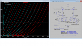
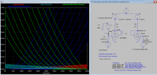
I wonder what is your folks opinion on g2 max voltage? There are some tubes that are mentioned with a 250Vdc max in their datasheet, but in triode mode, it can be higher. What we're looking at is g2 current and power dissipation when the plate swings well below g2.
I'm asking this because I'm designing UL+CFB output stages. The problem is, for some tubes to conduct enough quiescent current, I need to increase g2 a bit above 250V. In the UL+CFB mode, the g2 swings a bit by the overall UL percentage, so it should be okay to increase it a bit, yes? Also, we're talking about music, so g2 overload should be happening at peaks only. What is your opinion on this?
I'm asking this because I'm designing UL+CFB output stages. The problem is, for some tubes to conduct enough quiescent current, I need to increase g2 a bit above 250V. In the UL+CFB mode, the g2 swings a bit by the overall UL percentage, so it should be okay to increase it a bit, yes? Also, we're talking about music, so g2 overload should be happening at peaks only. What is your opinion on this?
How about g2 in a power tube run on triode mode? I've read that V plate can be high and consequently the V screen (apart a standard often used 100R resistor), so well over its max specs without the screen itself being damaged.
Anyone could explain that? And what would be the right behaviour than one must follow on U.L. mode?
Anyone could explain that? And what would be the right behaviour than one must follow on U.L. mode?
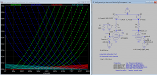
Food for thought. Just plot screen current of triode mode with Vg2 225V and 450V. The kinks are more pronoun when Vg2 is at the plate potential, Ig2 is exceeding power dissipation (unconfirmed), triode curve shifted to the left by about 35v
Attachments
Last edited:
How about g2 in a power tube run on triode mode? I've read that V plate can be high and consequently the V screen (apart a standard often used 100R resistor), so well over its max specs without the screen itself being damaged.
Anyone could explain that? And what would be the right behaviour than one must follow on U.L. mode?
Some tubes have a triode-connected value quoted. For example, with an 807 G2 and plate can be 400VDC.
I am also a little mystified by all the criteria to consider when G2 may exceed limits, for example in an ultralinear configuration. Since G2 current is proportional to plate current, it should be possible to infer dissipation, and verify that is within limits, and then using a screen resistor keeps the voltage in check.
What is really confusing for me is that some makes of tubes tolerate abuse better than others, so there is an element of suck it an see.
I want to build this circuit ...
Brimar 25P1
... but the B+ is 440VDC, and the 5B/255M tube is meant to be an 807 on an Loctal base, so I don't see how it works. But it came from the manufacturor of the tubes.
Almost every North American FM station is constantly "clipping off" high frequency content and has for decades. Including classical and jazz stations. It's built into the processing architecture.My first rule for Hi Fi playback of recorded sound:
If it is clipping, it does not sound good, turn it down..
While not ideal minor short term clipping of dynamic material can be inaudible if the circuit is otherwise stable. There is no valid engineering reason for accepting poor circuit behaviour under overload, especially with the inherent limitations of a 2 watt amp. Unless you own K-horns.
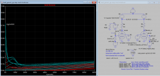
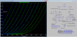
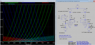
These plots are more accurate than previous, I need to revise the simulation, using zener diode is easier than using equations.
Attachments
Last edited:
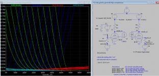
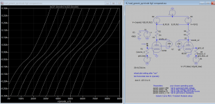
The screen grid2 current has been adjusted downward, dissipation appears with 9W limit. If the screen voltage is reduced the dissipation is lower, there is no Vg2 current curve in the datasheet, but it said not more than 15mA, it depends on the operating points.
Attachments
Last edited:
Some tubes have a triode-connected value quoted. For example, with an 807 G2 and plate can be 400VDC.
I am also a little mystified by all the criteria to consider when G2 may exceed limits, for example in an ultralinear configuration. Since G2 current is proportional to plate current, it should be possible to infer dissipation, and verify that is within limits, and then using a screen resistor keeps the voltage in check.
What is really confusing for me is that some makes of tubes tolerate abuse better than others, so there is an element of suck it an see.
I want to build this circuit ...
Brimar 25P1
... but the B+ is 440VDC, and the 5B/255M tube is meant to be an 807 on an Loctal base, so I don't see how it works. But it came from the manufacturor of the tubes.
Ok, for what I understood until now in triode mode plate surface has the major area than screen and if they are tied together (=same V) electrons are most in the plate. So the screen can tolerate some more V than specs.
In case of UL things appears to me more complicate, because also of UL% contribution...I don't know.
For the 5B/255M circuit you posted indeed the tubes run at +40V than max operating values, I can't say how it comes out. They can be "pushed" over without negative effects.
- Status
- This old topic is closed. If you want to reopen this topic, contact a moderator using the "Report Post" button.
- Home
- Amplifiers
- Tubes / Valves
- Importance of Screen Voltage of Pentode???