But if I choose a lower g2 voltage, the curves change, voiding the choice of operating point and load I decided on based on the curves. No?
In other words, are the curves given by the manufacturer actually useful in choosing an operating point or does every good designer toss the data sheet and make their own set?
In other words, are the curves given by the manufacturer actually useful in choosing an operating point or does every good designer toss the data sheet and make their own set?
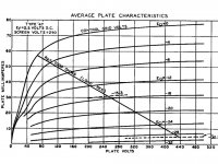
Both are done on the data sheet curves. The graph on the left is my choice (Vp 162.5, Ip 52mA, Vg1 =-10 , Rl = 3k25.
The graph posted on the right is meant to be an approximation based on the operating point suggested by sser2 in answer to my question "If you were going to build based on these curves, where would you set your operating point?" His answer was Vp250 (withVg2=250) , Vg1= -15, and load of "500V / 80mA = 6.25K (approximately, by eyeball)"
As for trying curves with lower g2. I don't know how to calculate that. I'd have to set up a jig and make my own from measurements.
The tube on your graph is not very linear to begin with. Load lines for different load resistances are all kind of compromised in one way or another: it is either more 2nd order distortion (decreased curve spacing towards the bottom right of the load line), or more 3rd order (decreased spacing at both ends of the load line). At one particular load value, 2nd order distortion becomes minimal, and this is what is recommended as optimal load. 3rd order distortion is low at low Rl, and it increases monotonously until load line crosses the "knee", after which it does not increase much further with Rl.
Pentode distortion cannot be regarded without simultaneously regarding power. With low Rl, distortion may seem low from the way the load line crosses the plate current lines, but what is important is how much distortion you get at certain power output. For example with 3.5K load, the maximum power is, say 2W at 5% THD. If the load is 6.2K, the maximum power is 3W at 7% THD. In the second case, distortion seems worse. But if you turn signal volume down so that power is limited to 2W, distortion will get down to 3%. Thus, although the 6.2K load looks worse on the plate curves, it performs better than 3.5K load at equal power.
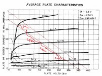
Here are the curves and load line for 47, which is a pretty linear audio pentode:
Pentode distortion cannot be regarded without simultaneously regarding power. With low Rl, distortion may seem low from the way the load line crosses the plate current lines, but what is important is how much distortion you get at certain power output. For example with 3.5K load, the maximum power is, say 2W at 5% THD. If the load is 6.2K, the maximum power is 3W at 7% THD. In the second case, distortion seems worse. But if you turn signal volume down so that power is limited to 2W, distortion will get down to 3%. Thus, although the 6.2K load looks worse on the plate curves, it performs better than 3.5K load at equal power.
Here are the curves and load line for 47, which is a pretty linear audio pentode:
Attachments
The tube on your graph is not very linear to begin with.
Yes, but because of that I'm getting a much better education from you than I likely would have if I started this with picture perfect curves. You're helping me to understand the basis for making the choices rather than a cut and past answer, which I'm not really interested in.
With low Rl, distortion may seem low from the way the load line crosses the plate current lines, . . .
I was actually using the distance between Vg1 lines. I think I see that they're not exactly equivalent at the upper left which tells a little more about the distortion around the knee.
3rd order distortion is low at low Rl, and it increases monotonously until load line crosses the "knee", after which it does not increase much further with Rl.
Just to check I understand your wording, by monotonously do you mean at a constant rate?
And also does that mean that on my load diagram if the Vg1 swing is kept between -5 and -15 the 3rd harmonic will stay relatively low? . . . And then that going more positive than that, the load line at the Vg1=0 curve indicates that 3rd harmonic will be higher because it is going through below the knee?
Attachments
....many comments online advising against operating a pentode with Vp much less than Vg2.....
There are "many comments online" about EVERYthing. Many of them are junk.
The #1 engineering objection to your plan is that you need a large amount of 162V and a small amount of 250V. Do you build a 250V supply for Vg2, then waste-off 90V at high current for plate supply? Do you build two supplies, one 250V one 160? Either way, your Product Manager objects to the cost. Most audio pentodes were designed to work well with Vg2 very near to Vp (or a bit less because Vg2 should be filtered better).
DIY economics is very different, true. Maybe we "like" building power supplies. The next issue is that as peak plate potential falls below typically 1/5th of Vg2, the G2 current goes way up. (Same reason a True Tetrode can't usefully swing plate below G2, but shifted due to G3 action.) Taken to extremes (guitar amps), G2 melts. If not melted, the reduced plate swing and G2 current-stealing reduces power output.
In general, a higher power amp may play lower power with lower THD. That means between a 6W 3%THD design and a 3W 2%THD design, there may be little difference at the 3W level, and the 6W plan will go a little louder before it goes "splatt". It rarely makes sense to aim at a lower power, even if the lower target has lower THD. Between similar plans of slightly different power, the difference may be much less than can be inferred from old hand-plots or SPICE models (both inaccurate at fine detail).
But sure: if you like Vp=160 Vg2=250, do it. Nobody will arrest you. You are not so far-out that any damage is likely.
2 "families" of screen-grid tubes
Dear all,
I think, we can separate 2 "groups" or "families" of screen-grid power tubes:
The first one allows for high g2 voltages sometimes up to 400-500V, equaling in many cases the plate voltage. These tubes are thus also perfectly suited for ultralinear or triode mode even at these high voltages. The entire KT and 6L6GC-family, as well as many standard European types (EL 34, 84, 156) can be counted into this group. These tubes are obviously also quite tolerant to non-stabilised screen voltages. They are the ideal tubes for pure Class A operation, and they are generally more "forgiving" at improper operating conditions.
The second group are the classical "sweep tubes" working originally as line (horizontal) deflection output tubes in the old time TV sets. These usually don't allow for screen voltages above ca. 250 V (although plate voltages may rise into the kV-range...) and they are very sensitive to screen overvoltage, increasing drastically the danger of internal arcing, due to a very close spacing of g2 to the control grid.
These tubes can also make very powerful and high quality amplifiers in pentode mode, but they need a clean and stabilised screen supply, also to ensure stable working points. Screen voltage variation of only a few Volts often has an enormous impact on plate current. Push-pull in Class AB - B is their usual mode of amplification, but this does not impair a lot their distortion behavior, which still is very good. Class A is only possible at relatively low plate voltages, as is Triode mode. Ultralinear operation is possible but usually needs a separated screen grid winding on the output transformer due to the huge differences between screen and plate voltages.
hope this helps ;-)
all the best
Uli
There are "many comments online" about EVERYthing. Many of them are junk.
I get that impression.
The #1 engineering objection to your plan is that you need a large amount of 162V and a small amount of 250V. Do you build a 250V supply for Vg2, then waste-off 90V at high current for plate supply? Do you build two supplies, one 250V one 160? Either way, your Product Manager objects to the cost. Most audio pentodes were designed to work well with Vg2 very near to Vp (or a bit less because Vg2 should be filtered better).
It's my objection too. But this first round is to learn what I can about the orientation to pentode circuit design as well as where the limits are and why.
DIY economics is very different, true. Maybe we "like" building power supplies. The next issue is that as peak plate potential falls below typically 1/5th of Vg2, the G2 current goes way up. (Same reason a True Tetrode can't usefully swing plate below G2, but shifted due to G3 action.) Taken to extremes (guitar amps), G2 melts. If not melted, the reduced plate swing and G2 current-stealing reduces power output.
Yeah, well, it's all interesting.
I find the bit about guitar amps encouraging. If they're known to do it then I feel enabled.
")
In general, a higher power amp may play lower power with lower THD. That means between a 6W 3%THD design and a 3W 2%THD design, there may be little difference at the 3W level, and the 6W plan will go a little louder before it goes "splatt". It rarely makes sense to aim at a lower power, even if the lower target has lower THD. Between similar plans of slightly different power, the difference may be much less than can be inferred from old hand-plots or SPICE models (both inaccurate at fine detail).
This is something that I had never thought about and appreciate hearing it from both you and sser2.
But sure: if you like Vp=160 Vg2=250, do it. Nobody will arrest you. You are not so far-out that any damage is likely.
I hope to get the time to build something in the next couple of months. Thanks for your helps..
in a pentode or a tetrode, it is not the plate voltage that controls cathode/plate currents...
in triodes, plate voltage controls plate current if grid voltage is held constant, this obvious from the plate curves...
so the G2 in pentodes and tetrodes are like the plate in a triode...
and there are now two ways to control plate and therefore cathode currents.
one, by varying the G1 voltage, and two, by varying the G2 voltage..
this is basic knowledge and analysis proceeds from here...
this is very important to remember....
pentodes have such high plate resistance and mu that they are often
ignored.....
Perhaps I'll experiment with it then. I have a spare power transformer that I want to use in a single ended pentode design, but it's 700Vrms (at 115V primary), which is giving me 500Vdc because I have 123V mains in my house. I want to use a 6550a or EL34 (interchangable), so I need to be careful how I design this.
Anyway, I don't want to high jack with that topic.
tube manufacturers paid people to get the operating points that work just fine,
they are all listed on datasheets for particular tubes, 6550a or EL34 are among them, it would be wise to follow these data as they were known a long time ago...
The important thing is that whatever g2 voltage you choose you maintain it. An unstable g2 voltage creates intermodulation, and could be part of the reason why pentode output stages are unpopular.
Wow such an old thread. Say I have a bunch of EL83s and have just build a SET amp in dual mono with 3XEL83s per channel in parallel on a 2.5K OT and that I'm blown away by the result.
Yet, I feel greedy for power and so do those huge OT's. Say I h8 UL and want to make those tubes run as pentodes: Could I just attach the G2 to the B+ with a high enough resistor to lower the voltage just enough below the plate ? What else could one do to stabilize the power ? How do they do it in general ?
P.S. I do have some really nice SFERNICE high stability precision resistors laying around.
Best.
OP
Difference in screen voltages changes shape of plate curves. For higher currents on lover anode voltages of course you want higher G2 voltages. But the drawback is, when anode voltage goes down with current G2 current starts going up sharply. G2 can be overheated and damaged. What matters, peak and average power dissipation of screen grids. Max screen grid current and max power dissipation are usually specified by manufacturers. Voltage does not matter, it is up to you to decide what is the best compromise between shapes of curves and reliability. Lower G2 voltage can be good as well for high swing linearity when the tube is loaded on high resistance. I usually stabilize G2 and G1 voltages of output tubes by solid state regulators.
Hello!
What kind of FETs would one use to make a solid state regulator ?
I see those transistors 78xx - Wikipedia but that stuff is limited to lower voltages.
Thanks.
... Say I have a bunch of EL83s and have just build a SET amp in dual mono with 3XEL83s per channel in parallel on a 2.5K OT and that I'm blown away by the result.
I don't like to say anybody has done anything if they haven't. No need for that. Keep it simple and ditch the EL83's. They aren't worth much and they were designed for TV service.
Oh dear. For a matter of fact I can say from personal experience in two different amp builds that you are very wrong about the EL83s. Trust me on my words.
I have built a single EL83 SET amplifier before the one I just mentioned and it sounds absolutely fantastic. If you compare the plate curves with the EL84 you will find that they are very similar. The el83 supposedly has denser screen grids but they are also specced at 2W dissipation.
The thing with EL83s is that I stumbled upon a stash of 60NOS (miniwatt DARIO and Paris made Mazda Belvu (that is Philips anyway))tubes for 80EUR on ebay. They are really cheap as NOS. Go and find 60's philips brand NOS EL84 at that price and be sure that they werent roasted in a guitar amp and resold at 80% emission?
They are really sweet tubes with marvelous soft and warm highs and some surprising low end as well.
I am well aware of the design of those tubes and that is beyond the point.
Yes they do have a significantly higher internal resistance VS the EL84s but from my listening impressions that makes them sound even tubier and more saturated/compressed. One would argue that higher slope would render them more microphonic but then again power tubes don't suffer from microphony significantly - and especially not in a low noise HiFi listening environment. Not to mention the impressive build quality of those EL83s.
So there goes my little secret, I did an EL84 SET amp too and the EL83s have absolutely nothing to shy away from them. They actually even sound sweeter. while EL84s have a slightly shout-ier character when compared.
Last edited:
Hello!
What kind of FETs would one use to make a solid state regulator ?
I see those transistors 78xx - Wikipedia but that stuff is limited to lower voltages.
Thanks.
Search Maida Regulator -- there are lots of implementations which limit the voltage across an LM317. Many threads on the MAIDA on DIYAUDIO.
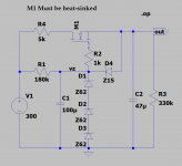
Here's a version of the screen regulator used by Pete Millett. M1 is an FQPF8N60 or similar:
Attachments
They are really sweet tubes with marvelous soft and warm highs and some surprising low end as well.
If they are a decent audio output tube then they have a flat frequency response and they don't have more or less of this and that, sweetness, warmth, low end, shoutiness, forwardness of mids, mellowness, ... that is all babble and is the product of the components and PS and speakers outside of a good output tube.
Forgive me, I just get this feeling so many people out there are self absorbed and obsessed with their engineering skills that they don't even care to listen and appreciate music and the tone! What is wrong with curves ? Almost everyone is obsessed with flat and linear...
Real tubes have curves<3
Real tubes have curves
<3
Last edited:
- Status
- This old topic is closed. If you want to reopen this topic, contact a moderator using the "Report Post" button.
- Home
- Amplifiers
- Tubes / Valves
- Importance of Screen Voltage of Pentode???