I can't find a datasheet on the B.. What's the difference? ........I wonder how far they can be pushed...
I originally found a big box full of "mystery tubes" in a large lot of tubes I got about 10 years ago. The box sat around until my curiosity caused me to plug them in about 3 1/2 years ago. There were multiple flavors of 3D21's in the box. There are two distinct styles, one with a 15 watt plate, and the other with a 40 watt plate. All other specs are identical. All have a dual 6.3 / 12.6 volt heater. The 7403 is a 40 watt version with only a 6.3 volt heater, and the 3D21WB is a 40 watt, dual heater version. All the others have 15 watt plates. I had some of each in the box, all used, some very used, and most turned out to be gassy. Some glowed blue, while others would go into a slow runaway.
I tested them starting in post #331 of the following thread.
The KT88 testing was in post #310 of the same thread.
http://www.diyaudio.com/forums/tubes-valves/133034-6l6gc-ab2-amp.html?highlight=6l6gc+ab2
I found four of the WB's locally, definitely used, but I'll try them. (basically it's something to plug in after the basic build, while I work on the regulators and figure out the pentode version of the amp)
On to the real project:
For the regulators... I found 10 maida regulator PCB's I forgot I ordered last winter. So, maybe I will go that route. I'm thinking SY's Red Light District 'simplified' maida screen reg.
Then a negative version for the bias supply. B+ won't be regulated.
For a regulated bias supply, when running parallel tubes, how do I balance them? Do I need a regulator for each tube?
The grid circuit should not draw much current, so you can just feed the negative voltage regualtor into the existing bias circuit on Petes driver board. My board is populated with the diodes and caps as Pete intended. I tie the positive output of the regulated bias supply to ground, and the negative output into either one of the bias inputs on the board. If you haven't populated the board yet, you could leave out the diodes, one cap and the resistor.
This works well for class A and AB1 use. All experiments done so far use this method. The beast with a box full of output tubes will need something different.
Down the road I plan to do some AB2 and screen drive stuff. For this I will use an external bias board with a mosfet and bias pot for each output tube.
I need a bigger dummy load
Quickly tried pentode and UL modes on the KT88 breadboard. Same conditions other than bias setting.
Pentode: 5% THD @ 76W, 1W THD 0.04%, 12W 0.6%
Ultralinear: 5% THD @ 79W, 1W THD 0.008%, 12W 0.1%
My dummy load started smoking after a minute at 79W
Quickly tried pentode and UL modes on the KT88 breadboard. Same conditions other than bias setting.
Pentode: 5% THD @ 76W, 1W THD 0.04%, 12W 0.6%
Ultralinear: 5% THD @ 79W, 1W THD 0.008%, 12W 0.1%
My dummy load started smoking after a minute at 79W
That's exciting. Hopefully you don't burn the house down for the holidays ") .
.
I'm slowly progressing on my gu-29 build.. I've got the screen and bias regulators ready. Just need a few resistors and tube sockets, and hope to order them tomorrow.
Pete, for parallel tubes, are you planning on treating all four as individual tubes? As in, 4 coupling caps, four bias settings? Or, are you planning on simply literally paralleling the output tubes? My tube matching ability is limited, so I think I'll need to go w/ setting bias on each section. (I'd basically duplicate the bias balance and divider pots for each pair)
For bias, I'm looking for about -25 to -30v for the 807's right?
Maybe I need to plot a loadline for the gu-29's to be sure I'm on the right track for my negative supply.
Happy Holiday!
.I'm slowly progressing on my gu-29 build.. I've got the screen and bias regulators ready. Just need a few resistors and tube sockets, and hope to order them tomorrow.
Pete, for parallel tubes, are you planning on treating all four as individual tubes? As in, 4 coupling caps, four bias settings? Or, are you planning on simply literally paralleling the output tubes? My tube matching ability is limited, so I think I'll need to go w/ setting bias on each section. (I'd basically duplicate the bias balance and divider pots for each pair)
For bias, I'm looking for about -25 to -30v for the 807's right?
Maybe I need to plot a loadline for the gu-29's to be sure I'm on the right track for my negative supply.
Happy Holiday!
Yes! I'm basically using Maida regulators for both. (Honestly not much thought in to why, other than I have 10 PCB's I bought a year ago, and might as well use them). Trying for one screen and one bias regulator per channel, sharing it between the tubes.
I'm using the screen supply from Sy's Red Light District amp. The Red Light District, p2
But, in my case for the gu-29's I need less voltage.. so on his schematic, the 200 ohm became 210, the 56k to 43k, the 180k to 150k. That gives me between 200 and 230v adjustment. (If someone thinks I should be going lower, let me know.. Datasheet says something like 225 for max, and most people say 200)
And, basically the same for the bias.. I'm still working on the final values for it, and will post them when I'm done.
I've got the PCB's from the thread "Maida Regulator PCB" here in the tubes forum. Page 4 describes parts selection for positive and negative regulators. Sy's got the layout for a PCB on page 4 of his rld site I linked to above, which should work, too (But the lm337 has a different pinout from the 317, so be aware of that if you make a negative supply w/ sy's layout)
As George mentioned, these might be a bit overkill, compared to the simple zener/capacitance multiplier circuit, but OTOH, parts are only a few bucks, and I already have the PCB's.
I'll post more as I progress.. (Nothing is tested yet)
Last edited:
My dummy load started smoking after a minute at 79W.....Hopefully you don't burn the house down for the holidays
Warning.....I was exploring the upper power limits on a pair of 6L6GC's when my old faithful dummy load went open. Before I could smack the kill button the open frame OPT was on FIRE.
Another possibility for parallel output tubes is the RLD approach. Since the grids are operated at the same DC potentials and the cathodes are paralleled SY employs a seperate screen adjustment for each output tube.
Another possibility for parallel output tubes is the RLD approach. Since the grids are operated at the same DC potentials and the cathodes are paralleled SY employs a seperate screen adjustment for each output tube.
Any pro/con to doing it that way?
It's basically the same thing, right?
PPP 807s
Hooked up parallel 807's (actually 807W/5933) on the breadboard.
Same driver as the KT88, with a little tweak to the bias circuit to lower the voltage. No effort to match the 807's, they aren't even the same brand. Tubes are directly paralleled (no separate bias).
Vp = 559V, Vg2 = 279V, Vg1 = -32V, Ik = 40mA/side or 20mA/tube, Pa = 11W per tube at idle.
1W THD = 0.03%, 12W THD = 0.20%, 5% THD @ 25.3V or 80W RMS into 8 ohms.
Square wave looks good but the amp oscillates with no load. May just need to put 100 ohms across the output, or maybe a screen bypass... needs investigation.
Hope everybody has a happy New Year!
Pete
Attachments
Played with the compensation to get the amp stable under no load/full load conditions. With no load, it was oscillating at 1MHz + 10Hz!
I needed to add another RC (1k & 470p, C9 & R27) on the first stage, change the feedback comp cap from 47p to 68p to kill the HF oscillation and properly damp the square wave response. Also increased the coupling caps to 1uF (first stage) and 0.22uF (output) to avoid the LF oscillation. This also reduced or eliminated the LF and HF response peaks I saw earlier. Its pretty flat now from 5Hz to 50kHz, but still has a 1dB peak at 75kHz.
Also added a 150 ohm 5W resistor across the output. Seems pretty stable now, at least with a resistive load from 4 ohms to open. Zout is 0.57 ohms (DF = 14).
If I increase the idle current up to 63mA/side (still only 18W/tube), 1W THD drops to 0.015% with a small penalty in max output power (74W vs. 80W).
Pete
Thanks a lot!! I'm very close to building this thing. Beginning to realize exactly what I've gotten myself in to.. (Transformers are huge compared to my previous projects)
Could you recommend to-220 diodes for the power supply? While searching I found the fancy new SiC rectifiers and thought I'd try those, but am confused.. (while it's rated for 2A, mouser has the continuous current listed as something like 50uA for those cree, which I don't understand). Even skipping the SiC models, I still don't know what to look for in a to-220 package.
Also, do I need to pay attention to voltage ratings on resistors? The KOA's are only rated up to 400v, the CC's I've got are rated to 350v. I was thinking I should add a 100ohm-ish resistor to the plate of each of the parallel output tubes, and would be exceeding the rating on any of these resistors.
I guess that's the only place in the amp that sees such a high voltage.
Oh, one more... Any speaker (driver) recommendations? My only speakers now are some high efficiency fostex.. I think they say they can take up to 80 watts, but something tells me they aren't going to sound great with a loud amp.
Thanks, and happy new year!
Last edited:
The fun begins! Done w/ decisions and pouring over data sheets, etc.
I went w/ the Cree SiC diodes.. I have discovered Mouser has a LOT of typo's in their product specs. I'll know if they work or not soon.
I should have the kt88 version up in no time. Then I'll build my regulators and get the gu-29 version running.
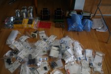
Aww, I've got no 7 pin sockets! Where's that package.. Guess it won't be this weekend
I went w/ the Cree SiC diodes.. I have discovered Mouser has a LOT of typo's in their product specs. I'll know if they work or not soon.
I should have the kt88 version up in no time. Then I'll build my regulators and get the gu-29 version running.
Aww, I've got no 7 pin sockets! Where's that package.. Guess it won't be this weekend
Attachments
Last edited:
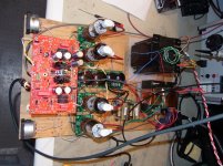
Yes, I had 5 motor runs already... So, decided to go all motor run. (power supply caps, and then even the 4 that are doubled up on the PCB are being replaced by 2 motor runs) Then I'm also using old soviet capacitors for bypass, etc, which are also huge (again, I've already got boxes of them, so might as well use them).. You can see a few towards the mid-top of the photo. This will be a very large amplifier! I want the final design to sort of showcase all the large components, so need to come up w/ creative chassis design. I may have to put glass sides around the monoblocks... I'm still far from putting a lot of thought in to that, though.
For iron, I'm using what Pete recommends on page 14 of this thread. I couldn't make up my mind about what to build, so let him do it for me (Thank you Pete.. else it could be next winter and I'd still be sitting here debating w/ myself on transformers)
If anyone else is doing the pentode thing, let me know.. I've built regulators for the bias and screen supplies. Am curious what others are doing.
The sad thing is, this may not even work.. I'm wanting to use gu-29's/829's, and it's not exactly a good idea. There are active threads right now about people unable to get them biased properly, and Pete mentioned feedback instability. I was going to use George's idea of separate screen regulators for each section, but the two sections share a screen.. I'm prepared to scrap them, and go w/ 807's though.
I was just thinking, all my existing amps have DC on the filaments..
Do I need to worry about that w/ PP and indirectly heated tubes?
For iron, I'm using what Pete recommends on page 14 of this thread. I couldn't make up my mind about what to build, so let him do it for me
(Thank you Pete.. else it could be next winter and I'd still be sitting here debating w/ myself on transformers)If anyone else is doing the pentode thing, let me know.. I've built regulators for the bias and screen supplies. Am curious what others are doing.
The sad thing is, this may not even work.. I'm wanting to use gu-29's/829's, and it's not exactly a good idea. There are active threads right now about people unable to get them biased properly, and Pete mentioned feedback instability. I was going to use George's idea of separate screen regulators for each section, but the two sections share a screen.. I'm prepared to scrap them, and go w/ 807's though.
I was just thinking, all my existing amps have DC on the filaments..
Do I need to worry about that w/ PP and indirectly heated tubes?
- Status
- This old topic is closed. If you want to reopen this topic, contact a moderator using the "Report Post" button.
- Home
- Amplifiers
- Tubes / Valves
- Mono push-pull driver PCB