I'll answer for him.. The transformers he used and published the info for in his last several posts has been w/ the dynaclone transformer.
Feedback is global.. same as the schematics on the website.
Feedback is what I was thinking about before falling asleep last night.. I may experiment for a while. I want to try local and e-linear. So far my build is going as per pete's schematic, other than i'm building voltage regulators. Once I start trying new things, I'll post what I find. I hope you all do the same") .
.
Oh, does anyone know if I can run the 12hl7 screens at 150v? I am struggling to figure out the screen dissipation. (First time trying to figure out pentodes) To me, it looks like I would still be safe, but I'm probably wrong.. else Pete would have done his testing w/ this tube at 150v.
Feedback is global.. same as the schematics on the website.
Feedback is what I was thinking about before falling asleep last night.. I may experiment for a while. I want to try local and e-linear. So far my build is going as per pete's schematic, other than i'm building voltage regulators. Once I start trying new things, I'll post what I find. I hope you all do the same
.Oh, does anyone know if I can run the 12hl7 screens at 150v? I am struggling to figure out the screen dissipation. (First time trying to figure out pentodes) To me, it looks like I would still be safe, but I'm probably wrong.. else Pete would have done his testing w/ this tube at 150v.
Last edited:
I may experiment for a while. I want to try local and e-linear
I tried introducing feedback from the UL taps to the driver plates, using 30k resistors. It works well, drops the gain a little and lowers distortion a little. Maybe a small loss of max output power. I also lowered the global feedback resistor from 30k to 22k to drop the gain a bit. Something like 0.008% THD @ 1W now. I was also looking at IMD last night and it looks pretty good too.
Oh, does anyone know if I can run the 12hl7 screens at 150v? I am struggling to figure out the screen dissipation. (First time trying to figure out pentodes) To me, it looks like I would still be safe, but I'm probably wrong.. else Pete would have done his testing w/ this tube at 150v.
The way I have things set up there is only 130V on the plates, so 150 might be pushing it. I tried 75V (0C2 VR tube) and 105V (6074/0B2), no difference seen in performance. Right now I have the 6074 in there (cheap, $2 at RES).
Pete
Some 807PPP measurements
Did some measuring today of the 807 PPP amp. Pretty much the same configuration as I posted before, with the addition of feedback from the UL taps to the driver plates.
Now running ~450V B+ - I discovered I was inputting 120V to the 100V tap of the PT primary, and getting ~525V B+. The power transformer seemed fine with this, BTW, at least at 60Hz. So the max output power now is reduced, 43W @ 5% THD, or 37W @ 1%. I may go back and make more measurements on the 100V tap
See the attached PDF file for graphs and a schematic of the driver as of today...
Feedback is your friend!
Pete
Attachments
I was just about to calculate using lower value resistors (r15 and the 10k's on the plates) to see if I could bring the voltage up a bit, and maybe getting away w/ the 150v screen regulator, but this definitely puts a stop to that.
(and thanks for bringing the voltage to my attention.. I was looking at the V on the old schematic and not thinking about the lower driver b+.. But now b++ is low enough I could potentially run the driver off it.)
That's a big difference in output power... Seeing all the crazy ways people use transformers (putting HV on 12v transformers, etc) I'm hoping we can get away w/ 120v on the 100v taps.
Thanks for the PDF!!
(how do you pro's manage inventory? Every minor component issue sets me back a week waiting for delivery... I tend to order double of everything, but have been doing that for years, and still never have what I need)
-edit- Pete, did you really change r6 from 47k to 4.7k? (I re-read your website this morning, and so just read the bit about using a large resistor there) Sorry for so many questions. I'm honestly far more experimental w/ lower voltage (not tube) projects.. But you know... fear of death and explosions, etc........
Last edited:
Pete, did you really change r6 from 47k to 4.7k? (I re-read your website this morning, and so just read the bit about using a large resistor there) Sorry for so many questions. I'm honestly far more experimental w/ lower voltage (not tube) projects.. But you know... fear of death and explosions, etc........
I did. Probably makes no difference at all... 47k just felt too big...
Pretty sure the kt88 works quite well as is.
I want to ask about the need for the additional feedback, and the not as good charts (High end drops off more, a bit more distortion) on the 807 version, compared to the kt88 charts on Pete's website w/ the Tango iron.
Is that because of the tubes, or the different, larger transformer? I'm just curious. I know it's a general rule that bigger iron means more high frequency losses.
I got my power supply built last night. The SiC diodes work fine. (Mouser does indeed get fields mixed up in their product specs. And omg, the amount of typo's and spelling issues I find just reading manufacturer datasheets is very bad.. yikes... Hopefully they get the numbers right!)
I'm thinking a PP or even PPP with 18GB5's outputs.....
maybe PPPP! I have 16 13GB5's mounted on perf board which will be used as two sets of 8 in a stereo amp. I intend to explore the upper regions of output power too, but I likely won't get back to it for about 6 weeks.
I will go back to the KT88 to double-check, but I think this same design will still work fine with KT88's.Hi, the version with KT88, is finished or still in progress?
As for a "real" build, I am going with parallel 5B/254M's:
An externally hosted image should be here but it was not working when we last tested it.
5B/254M @ The National Valve Museum
(Just an 807 in a lovely loctal base)
Pete
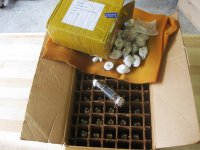
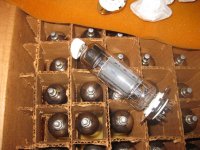
What about a PPPPPPPPPPPPPPPPPPPPPPPPPPPPPPPPPPPPPPPPPPPPPPPPPP 13GB5 amp? Here is a pic of 50 in this box, I have another 50 in another box from Rogalski's at 50 cents each in quantities of 100. Says "Made in USA", not sure if these are the "big power" 13GB5's or not.
The nine pin sockets were 35 cents each and the plate caps 30 cents each from Goodcomponent.com. Shipping almost doubled the cost but still a deal. The sockets are #GZC9-2-F and caps #MCV. Caps fit the top nipple but do not shroud the whole thing.
The nine pin sockets were 35 cents each and the plate caps 30 cents each from Goodcomponent.com. Shipping almost doubled the cost but still a deal. The sockets are #GZC9-2-F and caps #MCV. Caps fit the top nipple but do not shroud the whole thing.
Attachments
I got it powered up last night.. Voltages all checked out, got the driver board set up, plugged in the output tubes (3d21wb's, for now). I turned up the bias and they biased properly, (put them at 40 ma) but I had a loud buzz. I turned it off for a quick checkout.. Moved some heater wires, etc. Then turn it back on.. It gets very loud. I look at the meters on bias, and they are pulling about 100ma! I turn the bias all the way down and they are still pulling 40ma! (first power up, w/ the bias all the way down, they don't conduct at all).
So, this morning b4 work I checked the bias voltage, and it's still fine.. (-80v is the max, which is how it was originally).
Now I'm stumped.. What would cause that? My first guess is it's the tubes.. For one, they came out of a huge bin of random unboxed tubes.. And 2nd I've got no plate caps and only have wires wrapped around the anodes.. Would the screen burn up if the plate got disconnected? And could a burned screen cause problems like this?
I had issues with some of my used 3D21WB's. The 5 new ones that I got from ESRC seemed OK but I didn't run them for long. Some of the used ones exhibited bias creep and eventual runaway. Looking back now I believe it was a grid current issue but I don't have an amp set up to play with it right now.
I have a box full of the small plate 3D21B's, but I think they will go to the hamfest next month. I still have way too much stuff in my house.
It is possible, and likely if the screen is connected directly to a power supply. I usually put a resistor in series with the screen. I undersize it (1/2 or 1 watt) during testing but use a 2 watt part for a final design. The resistor will smoke if the plate goes open. The screen will glow white hot before it fries, so it is usually obvious.
I have a box full of the small plate 3D21B's, but I think they will go to the hamfest next month. I still have way too much stuff in my house.
Would the screen burn up if the plate got disconnected?
It is possible, and likely if the screen is connected directly to a power supply. I usually put a resistor in series with the screen. I undersize it (1/2 or 1 watt) during testing but use a 2 watt part for a final design. The resistor will smoke if the plate goes open. The screen will glow white hot before it fries, so it is usually obvious.
Thanks George. One of the tubes was causing trouble.. Now it's all good
The horrible BUZZZ I had was a bad connection at the input ground.
Bias is still crazy.. As they burn in I have to keep turning it down.. a lot.. and the balance drifts all over the place.. One tube pulls about 1.5x the current for the first few minutes of operation, as it warms up. But.. that's all probably par for the course.. I'll let these burn in for a while.
WooHoo! I suppose I'll start building my regulators and get the other channel built w/ the gu-29 version.
FYI, I didn't pay attention to the amp for 10 min, and the current was up at over 100ma per side for a while.. Over 50watts. The tubes showed no signs of stress.
I've got two versions of this built and have been trying to decide which is the best... It's difficult! They are both similar enough that I can listen to them as a stereo set, and different enough to tell the differences between the no feedback triode version and the pentode (or tetrode) version. Basically everything every other thread has said on the topic is true. I think I like the triode a tiny bit more.. I think the pentode version sounds clearer, crisper.. It's probably technically better. Since it was my plan from the start, I think the 829 version will win.
What surprised me the most is the two versions are much more similar than different.. (I suppose that's how it should be.. we want to hear the music, not the amp)
If anyone is curious, these are my parameters:
7403 (kt88-ish) triode
492 on the plates
-57v on the grids 70ma
243v on the drivers. Drivers are triode too.
829 (807-ish) PPP Pentode (Or should I be saying Tetrode?) Regulated bias and screen supplies
590 on the plates
-28v on the grids 60ma
215v on the screens
305v on the drivers and 150v on the driver screens
UL to driver plate feedback, as well as global feedback. I decreased the global feedback a little after I added the ul to plate feedback. (the all triode amp was louder! and, I do like the sound of less feedback)
And actually, I dont have test equipment to really get in to it, but I did find the amp much more "listenable" after adding the UL to plate feedback.
I suppose I have one question.. Should the 10m45's be hot? As in, turn the amp off, let it discharge for a few minutes, and I still can't touch the heatsink for more than a second. Someone else has my IR thermometer right now, so I can't be more precise than that...
Last edited:
- Status
- This old topic is closed. If you want to reopen this topic, contact a moderator using the "Report Post" button.
- Home
- Amplifiers
- Tubes / Valves
- Mono push-pull driver PCB