If the AC currents are equal (but opposite) then there is negligible modulation of the HT voltage, so you get a cleaner power supply.
The AC voltage at first tube anode, in case of line stage, is typically 1...2 Vrms.
If the anode resistor is 100 kohms, the AC current is some 10...20 micro amperes.
Assume we have a typical circuit where 22...100 uF electrolytic capacitor is used to filter the +Ub supply.
I ask: is there any sense to concenrate to compensate this 0.02 mA AC current ?
Apart from that, the AC-current of the 2nd triode depends on the load impedance as well, not only on cathode resistor.
Until the grid arcs to the cathode...
Yes, this could happen, but I have never heard or experienced. Have you ?
Yes, this could happen, but I have never heard or experienced. Have you ?
Yes. That's why I always include some sort of clamp (a diode or a neon bulb) between grid and cathode of tubes used that way.
Yes. That's why I always include some sort of clamp....
Interesting.
Please tell me more and in detail. What tube(s), what +Ub, etc.
Has this happened to you personally or have just heard this happening to others ?
12AX7 and 320V or so. I was doing preamp mods to help pay my way through school, and early conrad-johnson units were my bread and butter. I did a line stage rebuild with a topology very similar to this one for about a dozen people. Three field failures, which I traced to this problem.
Three field failures, which I traced to this problem.
I see. What happened to the tube ? How did it damage ?
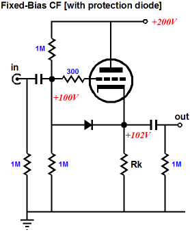
Example of grid-cathode protection diode:Hi all!
To be clear, give the show a schematic !!
Regards
It is very difficult to see why this sort of circuit could get the tube damaged without a diode.
There is a voltage divider at the grid ( 2 x 1M ), thus the maximum voltage can not exceed half of the +Ub. Also the current that could "burn" the grid-cathode connection is limited by 1M resistor.
Is this a bit over design ?
There is a voltage divider at the grid ( 2 x 1M ), thus the maximum voltage can not exceed half of the +Ub. Also the current that could "burn" the grid-cathode connection is limited by 1M resistor.
Is this a bit over design ?
Probably. That diode adds almost 3 cents to the cost. I would agree, the size of the resistors makes this safer (my failed units had 100k plate resistors), but at what point does the reliability get better? 200k? 300k? 200V? 300V? For a couple of cents, it is not really a big deal to have that protection.
I would agree, the size of the resistors makes this safer (my failed units had 100k plate resistors), but at what point does the reliability get better? 200k? 300k? 200V? 300V? For a couple of cents, it is not really a big deal to have that protection.In my experience preamp valves are at risk of grid-cathode arcing when the grid gets much more than 100V away from the grid. Doesn't really matter what the source resistance is, pretty much any arc is going to make a mess of your cathode material- its only weeny after all.It is very difficult to see why this sort of circuit could get the tube damaged without a diode.
There is a voltage divider at the grid ( 2 x 1M ), thus the maximum voltage can not exceed half of the +Ub. Also the current that could "burn" the grid-cathode connection is limited by 1M resistor.
Is this a bit over design ?
Probably. That diode adds almost 3 cents to the cost.I would agree, the size of the resistors makes this safer (my failed units had 100k plate resistors), but at what point does the reliability get better? 200k? 300k? 200V? 300V? For a couple of cents, it is not really a big deal to have that protection.
Mainly I try to understand why such a robust metal construction like the grid of the vacuum tube can get shorted due such small current (0...4 mA) that flows thru 100...200 k resistor and grid to cathode.
I have always thought that arching needs essential amount of current to happen.
In case of tubes the current is minimal.
In case of semiconductors this is clear.
- Status
- This old topic is closed. If you want to reopen this topic, contact a moderator using the "Report Post" button.
- Home
- Amplifiers
- Tubes / Valves
- High-End preamplifier with ECC82!