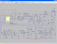
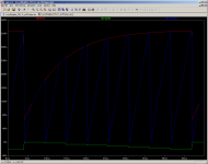
Here is a completed first pass.
It still needs a little tweaking.
I think 16 steps is too many to be useful, and should be changed to 8 steps.
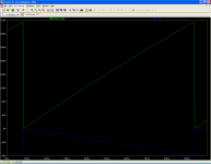
I used a faster sweep rate than line frequency to help with persistence on a scope.
No screen drive is included as it is held constant while sweeping the anode and stepping the grid.
The FETs in the simulation are only 250V parts and the bias will possibly shift when changed to 400V or greater parts.
One downside to this design is that it must be adjusted if the anode voltage is changed.
It still needs a little tweaking.
I think 16 steps is too many to be useful, and should be changed to 8 steps.
I used a faster sweep rate than line frequency to help with persistence on a scope.
No screen drive is included as it is held constant while sweeping the anode and stepping the grid.
The FETs in the simulation are only 250V parts and the bias will possibly shift when changed to 400V or greater parts.
One downside to this design is that it must be adjusted if the anode voltage is changed.
Attachments
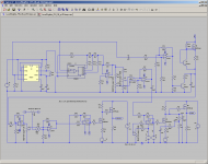
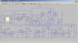
Fixed several problems. The anode sweep has to go each grid step, not once for the complete set.
FETs now IRFI744 good to 450V.
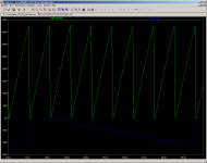
Grid drive in 8 steps now.
One issue is that there is no current limit to protect the tube at low grid voltage. This could be a problem.
Grid voltage is adjustable up to -80V and only goes to 0V. No positive grid drive. A pot can be added to allow the minimum voltage to be set to other than 0 Volts.
There are two pots in the step generation circuit (U13 and U5). U13 allows steps to -80V, U5 only adjusts to -20V, but allows adjustment down to 0-1.75V in 0.25V steps for small signal tubes.
FETs now IRFI744 good to 450V.
Grid drive in 8 steps now.
One issue is that there is no current limit to protect the tube at low grid voltage. This could be a problem.
Grid voltage is adjustable up to -80V and only goes to 0V. No positive grid drive. A pot can be added to allow the minimum voltage to be set to other than 0 Volts.
There are two pots in the step generation circuit (U13 and U5). U13 allows steps to -80V, U5 only adjusts to -20V, but allows adjustment down to 0-1.75V in 0.25V steps for small signal tubes.
Attachments
Last edited:
I was back in the ER for chest pains the last few days so I've not been on line (Had a heart attack and then a stent put in about three weeks ago).
I may try to breadboard parts of it, but I doubt I'll build the whole thing. I may just order one of the MODULE LAMPEMETRE ANALYSEUR - VACUUM TUBE ANALYZERs as it would save me a lot of time.
Conceptually I don't see any reason it would not work.
I expect it would take some tweaking to get the ramp reverence points set as the FET Vgs tends to vary a bit, but the adjustments in the circuit should take care of this.
Is there any portion in particular you are interested in/concerned about?
I'm glad you are back and ok then ")
I'm in the process of adapting the Sussex valve tester circuit and was considering in adding a tracer circuit. I bought the module you mentioned as I'm keen to use the PC to record the curves as well. Either way I was interested in building this as well as it looks like a good design to try...
Cheers
Ale
This is more of an exercise for me, as I've ordered the MODULE LAMPEMETRE ANALYSEUR - VACUUM TUBE ANALYZER.
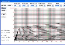
I added an SOA (Safe Operating Area) limiter to control the anode supply as I don't see any other practical way to protect the tubes from excessive dissipation at low grid voltages.
The plot shows grid steps in green and anode voltage in blue with the SOA limit in red.
If anyone sees any errors or oversights, please speak up.
Power dissipation dictates all the output FETs have heat sinks.
As is the drivers will need to be on heat sinks as well. However I think the load resistors of the drivers can be increased and made large enough to allow them to run without heat sinks. The changes may require tweaking other components.
Attachments
I've started breadboarding some of the circuitry.
I used a CD4060 instead of hte NE555 and CD4020. The 4060 has an oscillator built in. I set it for 16X the desired frequency and used the Q4, Q5, Q6 outputs. I used an OPA2131 for the inverter and a buffer with +/-15 V supplies.
Works fine except some noise from the digital section. I'm going to isolate the digital ground from the analog ground to see if I can reduce the noise.
First look at linearity looks good, but I"m using 0.1% resistors so it should be.
I have added some anode curves using Alain's great curve tracer board at my website here:
http://www.bartola.co.uk/valves/
You can find examples of 6CB5A, 6SL7GT, GU-50 and others
Cheers,
Ale
http://www.bartola.co.uk/valves/
You can find examples of 6CB5A, 6SL7GT, GU-50 and others
Cheers,
Ale
The cool and very advantageous things about making your own tester are:
You don't have to test every type ever made in the galaxy, and,
You can test at or very near the actual operating point of your circuit, which commercial testers almost never do.
I have a great fascination with old orphan nonaudio tubes, some of which have really killer chars, and can be gotten for nearly free, especially in larger quantities. Here's my tester for small signal miniatures, 6GK5, 6T4, 6AQ5, li'dat.

It's built on a breadboard, with the adjustment parts, like dropping resistors out available

I can reconfigure it for the victim of choice in a few minutes, and then test and match dozens (or hundreds) of the little buggers so I have better than 1% pairs and quads.
Poinz
AudioTropic
You don't have to test every type ever made in the galaxy, and,
You can test at or very near the actual operating point of your circuit, which commercial testers almost never do.
I have a great fascination with old orphan nonaudio tubes, some of which have really killer chars, and can be gotten for nearly free, especially in larger quantities. Here's my tester for small signal miniatures, 6GK5, 6T4, 6AQ5, li'dat.
It's built on a breadboard, with the adjustment parts, like dropping resistors out available
I can reconfigure it for the victim of choice in a few minutes, and then test and match dozens (or hundreds) of the little buggers so I have better than 1% pairs and quads.
Poinz
AudioTropic
Last edited:
Hi Poinz.
Interesting circuit, but could do with some inprovement.
By measuring the anode output voltage swing you are applying lots of negative feedback which will make close matching difficult.
You really want to keep the anode volts constant, then read the change of current by monitoring the volts across the cathode resistor, say 10R.
You will need to supply negative bias, which you can get from the spare rectified 18V output.
Now all you need is an oscilloscope to monitor volts in versus cathode current and you have gm displayed (scope in XY mode).
An altogether much more satisfactory instrument.
Regards
Henry
Hi Ale.
Are you still going to the audiojumble at Bracknell on the 17 April?
Regards
Henry
Hi Henry, I was planning to and looking forward to it, but am afraid that I'm traveling today for some time and won't be back on time. It would have been a good opportunity to meet...
Cheers, Ale
I purchased the same tester RE 604 introduced here some time ago. My test results show that it is not working properly with tubes having high transconductance and high current. The cathode current of the tube is measured over 10 ohms resistor placed between cathode and ground. In such case the high cathode current, say 50 mA generates -0,5 V additional grid bias, which is considerable at lower grid voltages. It seems that this effect has not been compensated in the test software.For example, if grid1 voltage is adjusted to -1 and the this causes 50 mA cathode current, the real bias voltage is -1,5 V, not -1,0 V as it should.I tested E180F tube, which has high Gm ( 20 mA/V). The error was some 25 % at low bias voltages compared with traditional (voltage- and current meters + separate DC-supplies) way of test.
Another source of error is the measurement of cathode current instead of anode current for multigrid tubes (tetrodes, pentodes, etc). One now has the screen current combined with the anode current which can introduce an appreciable error (20%).
I've switched to the digital domain in my playing and have a 89C51AC2 running with two D/A converters and four channels of A/D. Performance is acceptable so hopefully my next step will be to build the high voltage control circuits to (1) control Grid voltage to -75V in programmable steps, (2) control anode voltage and sweep it from 0 to say 400V?? while holding the screen constant, and (3) then figure out how to measure the anode and screen current without effecting their voltages or blowing things up.
If I restrict the anode and grid2 voltage to 270V, I could use AD629 IAs with 1 ohm sense resistors and measure the current directly. That puts a servere limit on the test set though.
Another thought was to use current mirrors with the sense resistor to ground, but I believe Current mirrors won't work well because of the poor balance at low voltages.
You can work out the ratio of anode to screen current from the valve specs so can keep the errors to below 2%.
Use a 1R resistor for the cathode and the grid bias errors also become insignificant, and if they are important then can also be calculated for.
Otherwise for these readings you will need individual meters for screen and anode, but then the readings will be static. Even so given the inaccuracies of the meters and reading them, you'd be lucky to get better then 2% anyway.
The datasheet ratio of anode to screen current varies with screen voltage
(and to a lesser degree anode voltage) so it would have to be a series of correction factors for the plots. Also using a ratio calculated from the data sheet I doubt you can keep the error below 10% considering valve to valve variation.
I believe I have found a way around the 270V limit of the AD629. I have a breadboard started and if it works I can measure screen and anode current directly with 10 Ohm sense resistors up to 500+ volts. 10 Ohm resistors in the screen and anode circuits should have a minimal impact on tube performance.
The negative current is not an issue other than the fact that one can not simply feed the A/D input directly. An inverting amp would solve the inverted sense issue.
It would however mean floating at least one ground for the HV supplies which I would consider a safety issue.
Another dissadvantage of return sensing would require two HV transformers which I'm trying to avoid (but may not be able to).
It would however mean floating at least one ground for the HV supplies which I would consider a safety issue.
Another dissadvantage of return sensing would require two HV transformers which I'm trying to avoid (but may not be able to).
Ok, What did I do?
I now know what is wrong and how to correct it.
Hint, It was NOT changing to a 1 Ohm cathode sense resistor and increasing the gain of the A/D amps by a factor of 10, although that may be a good idea any way.
I will tell Alain what I did first before I post here.
I now know what is wrong and how to correct it.
Hint, It was NOT changing to a 1 Ohm cathode sense resistor and increasing the gain of the A/D amps by a factor of 10, although that may be a good idea any way.
I will tell Alain what I did first before I post here.
Attachments
- Status
- This old topic is closed. If you want to reopen this topic, contact a moderator using the "Report Post" button.
- Home
- Design & Build
- Equipment & Tools
- Valve testing machine