I emailed Alain, so I will "spill the beans"...
Attached is a file of several scans.
The first sweep is a test with a 220R resistor to check the lineriazation of the A/D and amps. ( I don't remember who recommended this but thanks. It proves the board is not the problem.)
I was testing the proposed 1 ohm cathode resistor change to decrease cathode degeneration, and saw basically the same results.
Thinking about the effect of G2 ( I was changing it and looking at the change in gm) I suddenly thought I might add capacitance to reduce the effective impedance of the supply, to help hold it up for a more stable g2 supply. When I did it helped. So, I decided to switch off the ac to the g2 supply off to see what would happen.
HA! The anode supply is line synchronized! As the line voltage drops to zero crossing there is no charging of the G2 supply cap. So the voltage sags, dropping the Gm of the tube, and the characteristic low beginning of the traces. As the trace progresses, the anode voltage increases (that is what we are plotting on the x axis) until the input voltage is sufficient to again begin charging the cap for the g2 supply, and Gm increases!
One needs a very stable (stiff / low Zo) supply for g2.
Isn't this a tad early for you Yves?
I think I will have a beer and call it a night.
I won't go to work tomorrow (Good Friday) and take a day off.
Niters all.
Oh, yea, I got a Ghost restore to work on my computer so I am back on line at home.
Attachments
Last edited:
I was testing the proposed 1 ohm cathode resistor change to decrease cathode degeneration, and saw basically the same results.
This is an other issue and does not deal with G2-voltage at all.
I made tests with hi-gm triodes and triode-connected pentodes.
Simply the 10 ohms cathode (current sensing) resistor is absolutely too big.
I have not had possibility to modify my Lampemeter yet, but will do this soon.
Anyhow, your observations are very useful.
What was the issue with the 10 ohm resistor?
I realize a cathode resistor will increase the effective anode resistance and reduce Gm, but didn't think 10 ohms would be significant. If it were significant I would expect it to reduce Gm and thus shift the pentode anode plots, but didn't see a significant shift when I changed to 1 ohm.
Maybe I'm testing tubes with insufficient Gm to see the effect as the tubes are all Gm <10.
What tubes were you testing?
Looks like I messed something up when I put the test set back together last time, as I just fried my screen supply. I just hope I did not damage the board.
I may not be testing any tubes for a little while.
Attachments
Last edited:
Hi Steven,
Sad to hear you burnt the screen supply. Hopefully your board is not damaged. otherwise, is the best excuse to keep on working on your design")
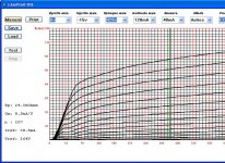
Here is my latest trace on EL34 in pentode mode. Gm is 10.75 and my screen supply is regulated with the addition of an 235uF cap
Need to find another pentode with gm>>10 to see what traces I can make with the board (unmodified as my cathode resistor is still 10 ohm)
Cheers,
Ale
Sad to hear you burnt the screen supply. Hopefully your board is not damaged. otherwise, is the best excuse to keep on working on your design
Here is my latest trace on EL34 in pentode mode. Gm is 10.75 and my screen supply is regulated with the addition of an 235uF cap
Need to find another pentode with gm>>10 to see what traces I can make with the board (unmodified as my cathode resistor is still 10 ohm)
Cheers,
Ale
Attachments
I modified my Lampemeter with 2,0 ohms current sensing resistor. Before that I made some tests to have the reference. I used soviet 6J9P (E180F) pentode as triode connected. It's Gm is some 20 mA/V. The difference is essential at higher currents.
In case of typical low Gm triode like 6N1P and 6N2P, there is practically no difference, which is very obvious.
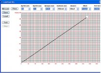
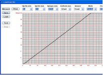
Below are my results with 6J9P and calibration curves for 32 mA and 256 mA as well.
6J9P triode connected, Rk = 10 ohms:
6J9P triode connected, Rk = 2,0 ohms:
Calibration curves for 32 mA and 256 mA (below):
In case of typical low Gm triode like 6N1P and 6N2P, there is practically no difference, which is very obvious.
Below are my results with 6J9P and calibration curves for 32 mA and 256 mA as well.
6J9P triode connected, Rk = 10 ohms:
An externally hosted image should be here but it was not working when we last tested it.
6J9P triode connected, Rk = 2,0 ohms:
An externally hosted image should be here but it was not working when we last tested it.
Calibration curves for 32 mA and 256 mA (below):
An externally hosted image should be here but it was not working when we last tested it.
An externally hosted image should be here but it was not working when we last tested it.
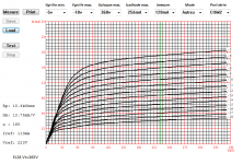
G2 Supply is replaced and I've gone through cal with two resistive loads. One for 32mA range and one for 256mA range.
The 6P43P looks better but still has some G2 Compression at low Va. It is supposed to be 7.5ma/V at 35mA Vg2=185V. I'm seeing a lot more gain than that as I'm only running 100V on g2.
Cal resistors are 1432 for high scale (256mA) and 10,150 for low scale (32mA).
Next I'll look at some higher gain tubes like the 6J49P (I think it is the highest transconductance tube I have).
Attachments
Last edited:
Does anyone else have problems with Gm reported too low in 32mA range?
I just tested a 6J9P (6Ж9П) and the test set reported 3.5mA/V and the 0 to V grid spacings were over 16mA apart and the 1-2 grid spacings were just under 16mA apart, which would indicate Gm around 16mA/V.
Ach! Never mind. Don't leave the measure point set to 2mA when testing a tube which should be measured at 20mA.
Duh.
Last edited:
I have 2 ohms cathode resistor. In addition to adjust the gain of the op-amps, I had to compensate the input offset voltage of the 32 mA amplifier.
At 4 mA measuring range the zero current level was shifted as below.
At 4 mA measuring range the zero current level was shifted as below.
An externally hosted image should be here but it was not working when we last tested it.
OK, I'll check that tonight.
How did you adjust your op-amp gain stages? Increase feedback resistor or decrease resistor to ground?
Changing the resistor to ground changes the input impedance, but with drive comming from the cathode it shouldn't matter except maybe with some small signal tubes at low current levels.
How did you adjust your op-amp gain stages? Increase feedback resistor or decrease resistor to ground?
Changing the resistor to ground changes the input impedance, but with drive comming from the cathode it shouldn't matter except maybe with some small signal tubes at low current levels.
I added parallel resistors to ground. 1k2 from pin 6 and 330 ohms from pin 2.
The compensation of input offset voltage required 2M7 resistor from pin 2 to +6,2 V.
Was your offset zero even if you use higher gain ?
I think the input impedance of the opamps remains the same since the input from current sensing resistor is at + pin ( 3 and 5) and feedback resistors are at - pin (2 and 6).
The input impedance should be Rfb || Rg, which is much greater than the source impedance of the sense resistor in parallel with the impedance looking into the cathode of the tube.
If I remember correctly I used a 585R resistor for the high gain circuit. so the imput impedance should be around 570 ohms. The missmatch should account ofor .2% error in the gain.
I wish the schematic and BOM matched the circuit board. It drives me nuts looking for components.
If I remember correctly I used a 585R resistor for the high gain circuit. so the imput impedance should be around 570 ohms. The missmatch should account ofor .2% error in the gain.
I wish the schematic and BOM matched the circuit board. It drives me nuts looking for components.
- Status
- This old topic is closed. If you want to reopen this topic, contact a moderator using the "Report Post" button.
- Home
- Design & Build
- Equipment & Tools
- Valve testing machine