I have mentioned in passing a mini-console project that I am working on. As I am getting ready to start drilling the chassis for the PA section I thought I would post the intended schematic including the preamp section. I am sure that some details will change as I test the results.
The preamp (12AX7 and 12AU7s) will be on a separate small chassis salvaged from a hammond L-101. Power supply will be 5AR4 rectifier with CLCLC filtering. The speaker drivers will be MA CHR-70 (series one) in BR tuned to get solid output down to a bit below 40Hz.
One concern is that some subwoofer amps may not be able to adjust crossover down low enough to avoid a boomy bump when trying to integrate with the mains. I may try to add a switchable HP filter to help with that.
Comments welcome.
Attachments

I just realized last night that this won't really cut it for my intended use. The primary input source is an iPod which in my experience has less output voltage than a CDP. I figure maybe 1V peak (1.4V RMS) which is no where near enough to drive this to full output.
It has been suggested to me that using pentode drivers would work better for the shade FB and I should think would also have more gain but I question whether even that would be enough. The preamp section above actually has a gain of slightly less than unity. I suspect that the easiest solution is to drill out an unused 7 pin socket on the preamp chassis and install an additional 9 pin socket which I could use for an additional gain stage (say 6N1P) immediately after the tone control section.
It has been suggested to me that using pentode drivers would work better for the shade FB and I should think would also have more gain but I question whether even that would be enough. The preamp section above actually has a gain of slightly less than unity. I suspect that the easiest solution is to drill out an unused 7 pin socket on the preamp chassis and install an additional 9 pin socket which I could use for an additional gain stage (say 6N1P) immediately after the tone control section.
Since your tone control is a negative feedback type you don't really need to drive it from a very low source impedance like a cathode follower. So an alternative would be to change the first stage into a common cathode gain stage.
Cheers
Ian
Cheers
Ian
Last edited:
Since your tone control is a negative feedback type you don't really need to drive it from a very low source impedance like a cathode follower. So an alternative would be to change the first stage into a common cathode gain stage.
Opposite, actually... Parallel feedback makes it look as if it is loaded on a virtual ground.
Opposite, actually... Parallel feedback makes it look as if it is loaded on a virtual ground.
With the circuit as shown that never happens. First each input leg has a 56K in series so the worst case load can never be worse than these two in parallel. Second, the feedback network is modified from the straight forward shunt derived shunt applied feedback by the addition of large series resistors from the sliders of the pots to the grid of the 12AX7. On that basis I would estimate the worst case load to be no less than 100K which a CC 12AU7 stage should have no problem driving.
Cheers
ian
With the circuit as shown that never happens.
Your guess is wrong again. Parallel feedback decreases input resistance. Ref: Ohm's law. 😉
Or, here is the picture I drew for students many years ago, to explain them feedback basics: hope it helps...
www.wavebourn.com • View topic - Feedback basics
Edit: similarly, U8 (6N1P) is loaded not only on 47K in parallel with 220K, but also on 270K/8 (I assume gain of KT-88 stage is 8). Plus, since gain of KT88 is non-linear, it is loaded on non-linear resistance.
Last edited:
I agree about U8 but I am referring to the NFB around U2 the 12AX7. Referring to your NOOBs guide to NFB that you so thoughtfully provided a link to, what we need to identify is the value of R1 in your little op amp circuit below, as that is effectivekly what defines the input impedance in this instance.
http://www.wavebourn.com/images/op_amp_neg.gif
Cheers
Ian
http://www.wavebourn.com/images/op_amp_neg.gif
Cheers
Ian
Although the input impedance of the tone control is reasonably high, as ruffrecords says, it does vary with both frequency and tone control position. At centre, LF Z is 181K (56K+125K), HF it is 43K (56K||181K). This is why it needs a low impedance drive. However, I would have thought that the anode impedance of a common-cathode 12AU7 is low enough to suffice - after all, this is not hi-fi!
Although the input impedance of the tone control is reasonably high, as ruffrecords says,
Actually, my correction was about the statement that input impedance is high because it is a tone stack in feedback loop. It was incorrect.
Since your tone control is a negative feedback type you don't really need to drive it from a very low source impedance like a cathode follower.
Yes, I agree that the tone circuit is loaded by a virtual ground. The issue is input impedance. This is high, but unfortunately too variable.
Note that the high value resistors from sliders to grid do not raise the input impedance, as the grid is not the virtual ground. The sliders jointly form the virtual ground. The high value resistors merely reduce the open-loop stage gain, and isolate the two pots from each other.
Note that the high value resistors from sliders to grid do not raise the input impedance, as the grid is not the virtual ground. The sliders jointly form the virtual ground. The high value resistors merely reduce the open-loop stage gain, and isolate the two pots from each other.
This discussion is very helpful. I do want to clarify that this is indeed intended to be high fidelity. Not golden ear necessarily but definitely not low fi.
Even if the impedance were not a problem I would think that one would rather have the tone control circuit before any significant gain to minimize over driving issue (esp. if 12AX7 is indeed used).
That said I am looking at some possible changes. Here is my thinking process.
1. Since the needed extra gain is not that great an additional low mu triode stage after the tone controls should be sufficient but the 12AU7 is not the most linear of tubes out there. The 6N1P and 12AY7 are much better but the gain is quite a bit higher than needed. So I immediately thought of the 6CG7. Nice linear novar based gain device and it can handle a good bit of signal swing on its grid.
2. Then I was considering the fact that the 6CG7 actually can handle a larger input signal swing than the 6N1P driver stage that follows it. That seems kind of backward so why not switch the two around and redesign the PA section for the 6CG7 as the driver. Depending on the data sheet one looks at the rp is either about the same to as much as twice that of the 6N1P. It would not be a bad thing at all for the rp to be a little higher it seems due to the schade. In fact if I am calculating it right there is not all that much feedback being applied as the 4k - 8k ohm v.s. 270k is a pretty small feedback signal. Of course, since it is an UL output stage, it may well be that no local feedback is really needed at all.
3. Now if we are using the 6CG7 for the driver and looking at using the 6N1P as the VAS at the end of the preamp section what other possibilities might be worth considering in this position? Since this is an all in one system there is some real benefit to low microphonics along with our linearity why not consider 12AY7 in the preamp? In my admittedly limited experience the 12AY7 does extremely well in the microphonics department. It also would have the added advantage of greater input signal swing capabilities if used in the place of the 12AX7 in the tone control circuit.
So what do you think of redesigning for 12AY7 for the CF input, CC tone control amp, the additional preamp VAS and even the CF subwoofer driver Then using 6CG7 to drive the KT-88 outputs with or without Schade?
I just read your original post again and I must admit my suggestions were based as much as anything on the (erroneous) assumption that the design was pretty much fixed and we were talking mainly tweaks to overcome problems. Now you are talking about sweeping changes including major changes to the tube types. I think you need to go back to basic engineering - write down a spec of what you actually want then design it.
Cheers
Ian
Cheers
Ian
Last edited:
The design had been through many iterations and I had thought I had things pretty settled and had in fact already drilled the power amp chassis when I realized that in switching from passive tone control to feedback tone control I had simply forgotten to account for the lost gain. Sort of a "doh" moment if you will. In the process of accounting for that problem some other possible improvements presented themselves so I want to consider the possibilities since I am making some changes anyway.
Some of these I would consider a tweak such as switching from 12AX7 to 12AY7 in the tone control. The basic topology wouldn't be changing just a hand full of resistors and plugging in a different tube. Similarly switching tubes for a CF is pretty minor. Of course adding the gain stage is more major but there is room to do it and the PS should be able to support it.
The basic design requirements are pretty well nailed down and the output stage pretty well set. Again tweaks in driver tubes and whether or not to use the P-P feedback are things that can be fiddled with in the Beta testing.
Requirements are:
- 5 to 10W SE output with bass and treble control of some fashion.
- High level inputs including integral iPod dock, RCA jacks and 1/8" headphone input.
- Output tubes and iron are purchased and pretty much set in stone. KT-88 and Edcor OPTs.
I think there is something to be said for reworking for low microphonics and wider voltage swing margins.
I did play around with simulations of the power amp sections a little bit this morning. I ran it without FB and with FB and as I suspected the amount of feedback as designed is pretty minimal (if the tube model is fairly accurate). The output level dropped only about 2dB.
A variation that I have seen a couple of places is to place a resistor between the driver plate and the junction of the feedback resistor and output tube grid. I tried it out using a 22k ohm resistor on the assumption that the rp of the 6N1P is in the 4k to 8k range and this added resistance should put it close to the 1:10 range suggested by Schade.
It changed the ratio of open loop to closed loop gain to almost exactly 6dB. The FFT results (I use only for comparative purposes and not to predict absolute values) indicated some improvement in HD2 and HD4 but interestingly little change in HD3.
I would think that the series resistance would mitigate the variability of rp some and thus improve distortion somewhat beyond just the higher feedback ratio.
I intend to play around a little bit with different cathode biasing schemes and other tubes as well before assembling a beta version of the power amp section.
Sorry. O. H. Schade. His paper on Beam Power Tubes includes a section on using local feedback with pentode tubes to get triode like characteristics and pentode output power. This plate to plate or plate to grid feedback is often referred to as Schade FB around here.
Otto H. Schade - Wikipedia, the free encyclopedia
I played around with the changes I mentioned and I do like the looks of the gain and headroom improvements. This is the last circuit that I sim'ed. A couple of notes.
1. All preamp tubes are 12AY7 simply for their good microphonics properties and linearity. I could be convinced to use something with higher gm if the microphonics are as good. As it is though the performance requirements don't seem that high in this application so it looks like they should do fine as is.
2. C12 is intentionally sized to reduce output below 30Hz to avoid wasting power on frequencies below that which the main speakers can really handle anyway. Since I now have plenty of gain I may even put a second order network in there instead. The sub amp output of course does not filter out these lower frequencies.
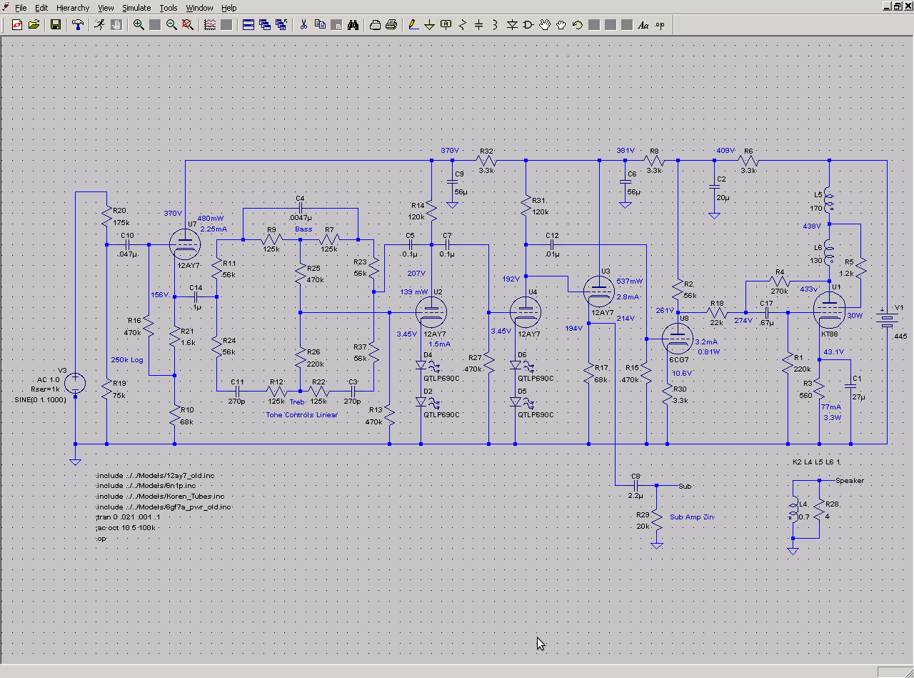
Any opinions gladly considered.
Another thing I wonder about is whether the input CF would perform better with voltage divider bias rather than bootstrap.
Oops, the 214V tag by U3 is bogus. I forgot to delete that label after the last round of bias adjustments.
Otto H. Schade - Wikipedia, the free encyclopedia
I played around with the changes I mentioned and I do like the looks of the gain and headroom improvements. This is the last circuit that I sim'ed. A couple of notes.
1. All preamp tubes are 12AY7 simply for their good microphonics properties and linearity. I could be convinced to use something with higher gm if the microphonics are as good. As it is though the performance requirements don't seem that high in this application so it looks like they should do fine as is.
2. C12 is intentionally sized to reduce output below 30Hz to avoid wasting power on frequencies below that which the main speakers can really handle anyway. Since I now have plenty of gain I may even put a second order network in there instead. The sub amp output of course does not filter out these lower frequencies.
Any opinions gladly considered.
Another thing I wonder about is whether the input CF would perform better with voltage divider bias rather than bootstrap.
Oops, the 214V tag by U3 is bogus. I forgot to delete that label after the last round of bias adjustments.
Attachments

Last edited:
BTW, not having a 6CG7 on hand and only one 12AY7 I checked the bias differences and it looks like substituting a 12AU7 (which I have tons of from a Baldwin) will only change bias by about 10% and so I think I will go ahead and build a beta test version using 12AU7 as the driver. I will only need to switch up the heater wiring when I get the proper tube.
I may also try doing a beta of the preamp using the tubes I have on hand by using the original schematic but adding the 12AY7 final gain stage and see how it goes. If the gain structure seems right then I can switch out a few resistors and move to all 12AY7 in the preamp if it still seems like the right thing to do.
Time to go digging through my parts and see if I have all the necessary passive components on hand.
Using 'Schade' (i.e. anode follower) feedback with UL is a bit like using both a belt and braces to hold your trousers up. I would use one or the other.
Putting the tone controls before any gain carries the risk of some thermal noise from the highish value resistors. Have you done a noise calculation, just to check it will be OK?
What do R19 and R20 do, apart from attenuate the input signal?
2dB feedback is not worth having. 6dB feedback is about the optimum amount for maximising high order distortion! You need either no feedback, or at least 15-20dB.
R19 and 20 represent the volume pot. I have not done a noise calculation. I put the tone controls first to reduce the amount of swing that U2 has to deal with. I could reverse the order if noise turns out to be an issue but I would have to be careful that the tone control tubes (primarily the second one) are not over driven.
As to belt and suspenders I plan to try it with and without the FB resistor. If it sounds just as good without I will dispense with it.
As to belt and suspenders I plan to try it with and without the FB resistor. If it sounds just as good without I will dispense with it.
OK - I should have spotted that R19 and R20 add to 250K. An active tone control does not have the same problem of overdriving that a passive tone control has, so it can go later in the circuit. A passive circuit has to boost everything, then reduce what you don't want. An active circuit only boosts what you want.
- Status
- Not open for further replies.
- Home
- Amplifiers
- Tubes / Valves
- Mini-console Schematic