Again I want to thank all of you for your assistance. Most recently DF96, I simulated the system with the gain stage first as you suggested and the results looked very promising. So I switched around again to the tubes that I have on hand to see whether it still seemed to be a good solution.
At first I forgot to switch to a single LED on the 12AX7 at the output of the tone control (from the two used for the 12AY7 version) and ran into trouble with lack of swing due to being biased to close to cutoff. When I realized my mistake I corrected the schematic and it seems to have plenty of swing to drive the output stage well beyond full output before overdriving any of the preamp or driver tubes.
So I will start assembling things using, as much as possible, the parts I have on hand to see how it performs. May take a while to build with my home schedule being what it is but I think we are on course now.
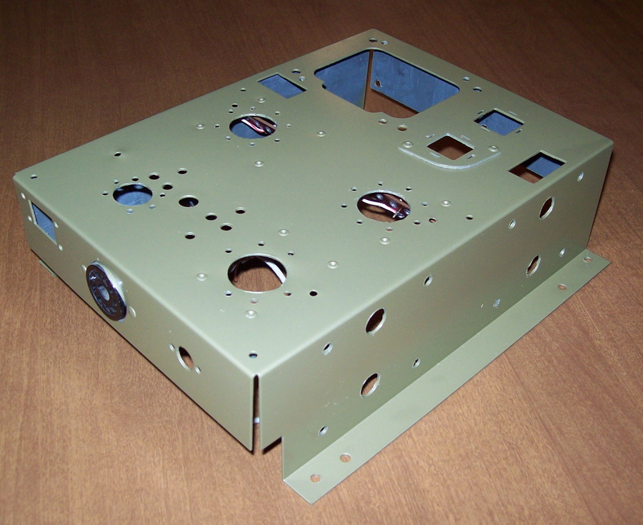
Have been quite busy (only one night last week at home) but lest you all think that I am doing nothing on this project I did get the power amp chassis fully drilled and painted. The paint is Rustoleum Metallic Sage.
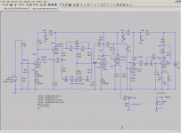
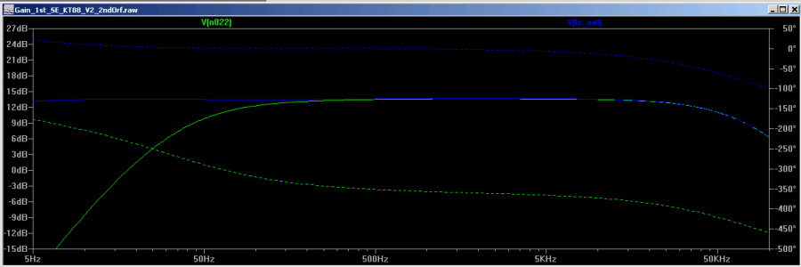
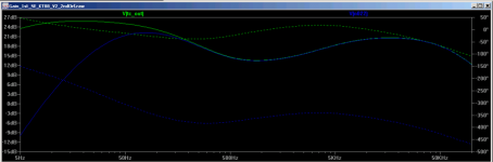
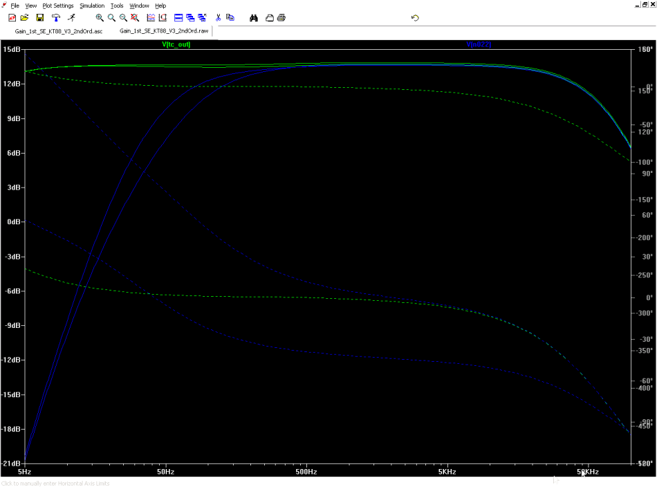
I also tidied up the schematic for the 12AY7,12AU7,12AX7,6CG7 version with a second order HP on the input to the power amp.
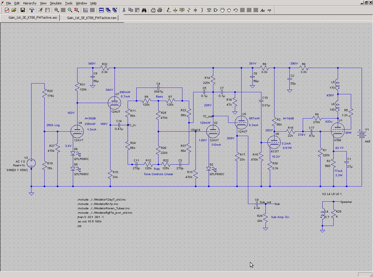
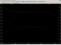
Showing the response before filter and after first and second stages.
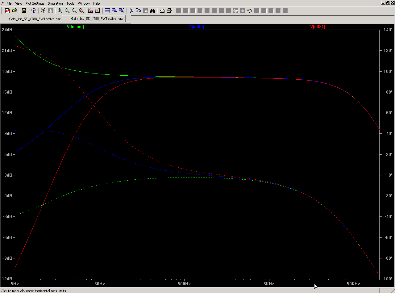
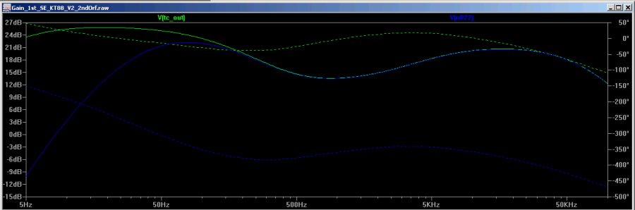
In looking at some simulation results at some of the interior nodes I noticed an interesting boost in subsonic frequencies at the output of the tone control section. I wonder if that is a real effect of some resonance or if it is an artifact of Spice...
Doh! Figured it out. I thought about it for a minute and it became obvious that C5 was too small.
I also tidied up the schematic for the 12AY7,12AU7,12AX7,6CG7 version with a second order HP on the input to the power amp.
Showing the response before filter and after first and second stages.
In looking at some simulation results at some of the interior nodes I noticed an interesting boost in subsonic frequencies at the output of the tone control section. I wonder if that is a real effect of some resonance or if it is an artifact of Spice...
Doh! Figured it out. I thought about it for a minute and it became obvious that C5 was too small.
Attachments

Last edited:
R16, C7, C10 and R15 (grid leak) comprise the 2nd order HP filter for main speaker protection.
OK, understood. I had somehow missed C10!
I am not sure you need to be so careful in the design of this HP filter. You seem to have carefully chosen the first stage components to be one tenth or ten times the second stage presumably to minimise interaction. Unfortunately the output impedance of the driving 12AX7 (probably around 50K or so) affects the turnover frequency of the first stage of the filter. Secondly the relatively low resistor value of 47K effectively throws away 6dB of gain and possibly increases the distortion of the 12AX7 stage.
In my experience there is in practice little disadvantage in making both stages of such a 2nd order filter the same. So changing C7 and R16 to 0.01uF and 470K respectively would probably work just as well and get you nearly 6dB more gain.
Just a suggestion.
Cheers
Ian
That didn't work out too well. Shifted the crossover way up. I did however switch the values in the schematic to 100k and 1M with appropriate cap values and that looked fine. Would at least give somewhat better loading. Given the FB applied to the 12AX7 the actual gain didn't really change with even the 470K load.
That didn't work out too well. Shifted the crossover way up.
When you say 'way up' just how far do you mean? 10%, 20% and octave?
I just modelled it with a 47K source and the -6dB point is 32Hz - just where it should be.
Cheers
Ian
Last edited:
Another week of "out every night" so haven't had time to resimulate. However, a couple of thoughts came to mind that I thought I would run by you. Since the tone control circuit uses plate to grid feedback on the 12AX7 is it possible that the effective Zout of the 12AX7 plate is significantly less than rp? If so would this make the loading less critical?
Also I could use a 6N1P instead of the 12AX7 in that position which has significantly lower rp. Of course the mu is much lower too which I suppose in theory anyway would have a negative impact on the performance of the tone control.
Thoughts?
Also I could use a 6N1P instead of the 12AX7 in that position which has significantly lower rp. Of course the mu is much lower too which I suppose in theory anyway would have a negative impact on the performance of the tone control.
Thoughts?
Another week of "out every night" so haven't had time to resimulate. However, a couple of thoughts came to mind that I thought I would run by you. Since the tone control circuit uses plate to grid feedback on the 12AX7 is it possible that the effective Zout of the 12AX7 plate is significantly less than rp? If so would this make the loading less critical?
The NFB will indeed reduce the output impedance of the stage. The question is by how much. With luck your 12AX7 will have a stage gain of around 50 and if your tone control is designed for unity gain with the controls central then you have 100% feedback and rp should be reduced by 50 times to say about 2K. However, if you turn the bass control right up you have say 20dB bass boost achieved by reducing NFB. So the closed loop gain at bass frequencies is now 10 and the stage gain (open loop gain) is still 50. So the output impedance (rp) is only reduced by the amount of feedback or 50/10 = 5 times to say 20K.
So yes the effective Zout will be lower but it varies.
Also I could use a 6N1P instead of the 12AX7 in that position which has significantly lower rp. Of course the mu is much lower too which I suppose in theory anyway would have a negative impact on the performance of the tone control.
Swings and roundabouts. There will be less open loop gain so rp will be reduced proportionately less. mu is about 35 IIRC so lets be generous and assume you can get a stage gain of 20. Mid band rp would be rp/20. Can't remember the rp for a 6N1P of the top of my head.
Cheers
Ian
OK I rechecked the simulations and using the same values did shift the crossover up by a bit more than an octave; maybe an octave and a half and the initial slope was shallower.
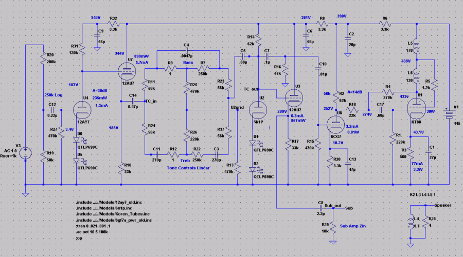
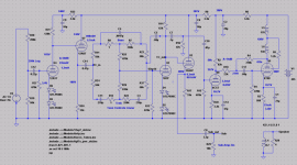
So I went ahead and simulated with a 6N1P and the original filter values. The schematic looks like this...
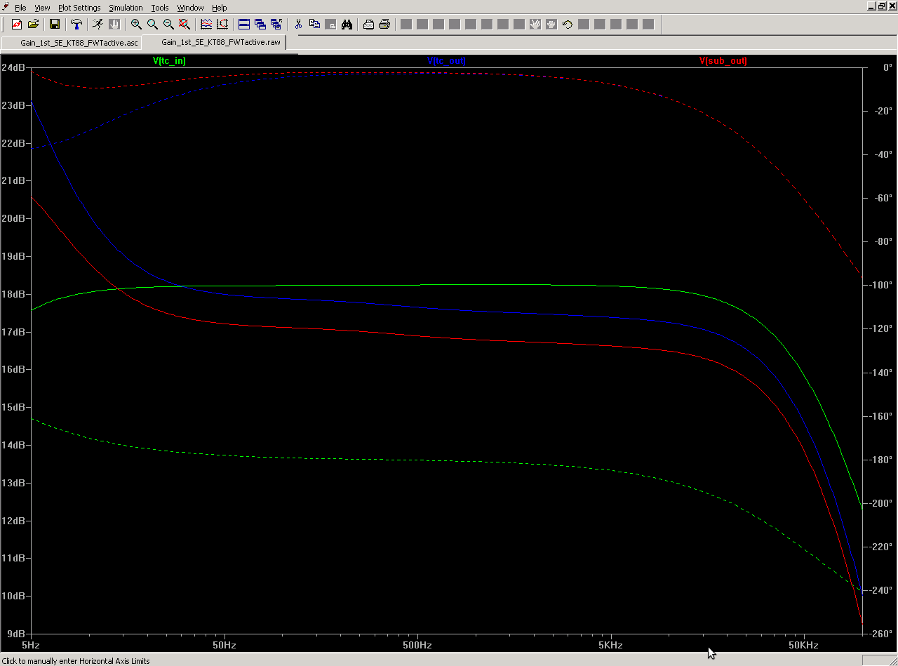
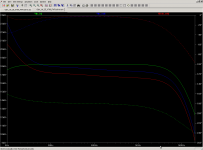
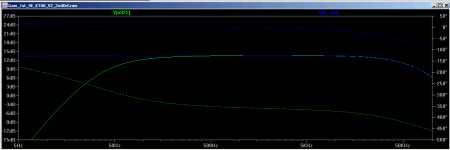
I ran some simulations of the response before and after the HP filter with the tone controls flat as well as at full boost and cut.
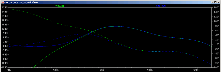
I had some concern that the lower mu of the 6N1P might affect the performance of the tone control section so I compared the results using the 12AX7 to that of the 6N1P and there was very little if any difference in the curves. To illustrate I superimposed the two cut curves to see how closely they track each other.
So I went ahead and simulated with a 6N1P and the original filter values. The schematic looks like this...
I ran some simulations of the response before and after the HP filter with the tone controls flat as well as at full boost and cut.
I had some concern that the lower mu of the 6N1P might affect the performance of the tone control section so I compared the results using the 12AX7 to that of the 6N1P and there was very little if any difference in the curves. To illustrate I superimposed the two cut curves to see how closely they track each other.
Attachments


OK I rechecked the simulations and using the same values did shift the crossover up by a bit more than an octave; maybe an octave and a half and the initial slope was shallower.
OK, just so we are clear on our terms, what exactly do you define as the crossover?
Cheers
Ian
In a second order I call it -6dB.
That's fine, that's what I call it too.
Cheers
Ian
Well, it wasn't as bad as I remembered (must be getting senile ") ) Here is comparison for 12AX7...
) Here is comparison for 12AX7...
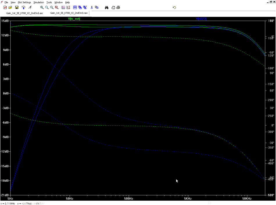
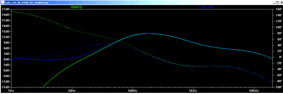
and 6N1P.
It amounts to about an octave which could easily be made up by jockeying the R value a bit. It does make for a bit more shallow slope though which wouldn't be fixed by that but it might be livable.
At the moment I think that using the 6N1P might still be the better option. It might also be possible to come up with a set of RC values in between the two as a compromise.
) Here is comparison for 12AX7...and 6N1P.
It amounts to about an octave which could easily be made up by jockeying the R value a bit. It does make for a bit more shallow slope though which wouldn't be fixed by that but it might be livable.
At the moment I think that using the 6N1P might still be the better option. It might also be possible to come up with a set of RC values in between the two as a compromise.
Attachments
- Status
- This old topic is closed. If you want to reopen this topic, contact a moderator using the "Report Post" button.
- Home
- Amplifiers
- Tubes / Valves
- Mini-console Schematic