Thanks, I have been meaning to fix that but I keep forgetting. That no doubt affects the speaker output. In this case however the signals that I was graphing are inside the amp at the plate of the 12AX7/6N1P and at the grid of the 6CG7 so other than any effect from the output stage feedback I don't think it is a factor in this particular thing.
Yes, they would.BTW, do you think that the KT99s would like a grid stopper?
")
I am also seriously considering putting a 100 ohm power resistor between the PT legs and the anodes of the rectifier given the tendency for modern rectifier tubes to have trouble with arcing over. It seems like it shouldn't pose any sonic problems given that this is an all SE class A so there shouldn't be any real issues of sag.
Just noticed that I said KT99 instead of KT88.
Anyway lest you think this is total vaporware... I have made some progress on knocking up the power amp chassis. Behold my ghetto version of the chassis cradle. Beats my normal method of propping it up with whatever junk I have on my work bench at the time.
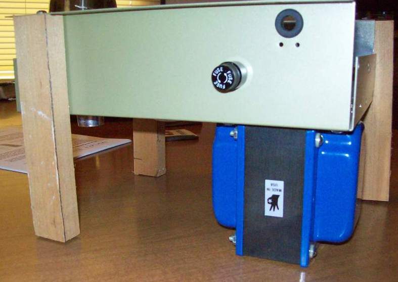
I rigged that up so that I can start mounting the iron and can cap.
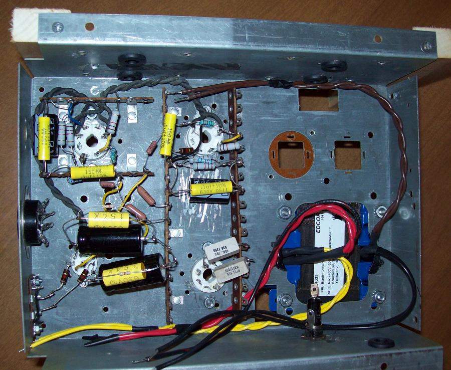
The two KT88s go on the top two sockets with the 6CG7 on the lower left and the rectifier on the lower right. You will note that the cathode caps on the 6CG7 are a lot larger than those on the KT88s (33u v.s. 22u). Seems a little bit backward I know but they fit better that way and both are sufficiently large for the application since there will be a 40Hz 2nd order high pass before the power amp input. Also having the smaller value on the output tubes may be better for blocking under overload.
You can't see it in the picture but the caps on the 6CG7 stick way up high so there is plenty of clearance below them. Notice that each electrolytic is bypassed by a polyester film cap (.15u for the 33u caps and .1u for the 22u caps). Since the resistors were not long enough to span the distance to the tag strip I used the big cap for that and then piggybacked the other components to it. Not neat but should be OK. The cathode resistors for the 6CG7 are carbon film instead of metal film only because I neglected to order the right ones. I had intended to use 3.3k but simulation indicates that the 3k that I had should be fine. A little less cathode voltage 9V instead of closer to 10V and 3mA instead of 2.8mA. If it doesn't work out at least they are easy to get to.
On the PT Brown is the 6V heaters, Yellow is the 5V and red is the B+ winding. Once the routing is finalized I will use plastic loops to cinch them down into place. The can cap will go in the hole without the insulator as it is farthest from the power and rectifier tubes (cooler). I intend to clamp all ground returns with an eyelet at the screw hole for the can cap's clamp.
The two 100 ohm power resistors on the rectifier are to provide some safety margin for the 5AR4 rectifier since I am using new manufacture Russians.
At the top you see the grommets for the leads from the OPTs which will be mounted on that side sticking out sideways. One PS choke will be directly under the PT and the other sticking out the side (back) using the same mounting bolts for each. The choke under the transformer will just clear the fuse holder (got lucky there).
You can see the 1k carbon comp grid stoppers on the 6CG7. They look old school but they are brand new. I also used them on the KT88s s well. The socket was so close to the input jacks that I figured that shielded cable was unnecessary. Hopefully I was right but we shall see.
Is there any reason why I should not twist the anode tap and UL tap from the OPTs together? It would make routing neater.
Appreciate any input that you have.
Anyway lest you think this is total vaporware... I have made some progress on knocking up the power amp chassis. Behold my ghetto version of the chassis cradle. Beats my normal method of propping it up with whatever junk I have on my work bench at the time.
I rigged that up so that I can start mounting the iron and can cap.
The two KT88s go on the top two sockets with the 6CG7 on the lower left and the rectifier on the lower right. You will note that the cathode caps on the 6CG7 are a lot larger than those on the KT88s (33u v.s. 22u). Seems a little bit backward I know but they fit better that way and both are sufficiently large for the application since there will be a 40Hz 2nd order high pass before the power amp input. Also having the smaller value on the output tubes may be better for blocking under overload.
You can't see it in the picture but the caps on the 6CG7 stick way up high so there is plenty of clearance below them. Notice that each electrolytic is bypassed by a polyester film cap (.15u for the 33u caps and .1u for the 22u caps). Since the resistors were not long enough to span the distance to the tag strip I used the big cap for that and then piggybacked the other components to it. Not neat but should be OK. The cathode resistors for the 6CG7 are carbon film instead of metal film only because I neglected to order the right ones. I had intended to use 3.3k but simulation indicates that the 3k that I had should be fine. A little less cathode voltage 9V instead of closer to 10V and 3mA instead of 2.8mA. If it doesn't work out at least they are easy to get to.
On the PT Brown is the 6V heaters, Yellow is the 5V and red is the B+ winding. Once the routing is finalized I will use plastic loops to cinch them down into place. The can cap will go in the hole without the insulator as it is farthest from the power and rectifier tubes (cooler). I intend to clamp all ground returns with an eyelet at the screw hole for the can cap's clamp.
The two 100 ohm power resistors on the rectifier are to provide some safety margin for the 5AR4 rectifier since I am using new manufacture Russians.
At the top you see the grommets for the leads from the OPTs which will be mounted on that side sticking out sideways. One PS choke will be directly under the PT and the other sticking out the side (back) using the same mounting bolts for each. The choke under the transformer will just clear the fuse holder (got lucky there).
You can see the 1k carbon comp grid stoppers on the 6CG7. They look old school but they are brand new. I also used them on the KT88s s well. The socket was so close to the input jacks that I figured that shielded cable was unnecessary. Hopefully I was right but we shall see.
Is there any reason why I should not twist the anode tap and UL tap from the OPTs together? It would make routing neater.
Appreciate any input that you have.
Attachments


I gave up on using embarq's free web site since it has such horrible restrictions on how you can format information so I set up an anglefire free site and will start posting a progress log there. You can go to the site in my signature and select mini-console to see my humble beginning.
Well, it is finally playing music (at least the power amp). I haven't updated my personal web page but just a quick update. I changed a few values such as the 6CG7 bias resistors to 3k instead of 3.3k as that is what I had available. Same with some of the caps. At some point I will update the schematic with actual values.
After wiring it all up I brought it up with no tubes in using a variac and checked PT winding voltages and all looked good. I used a 3A fast blow fuse for the testing. When this checked out I put in all of the tubes (KT88 and 6CG7) except the rectifier just to make sure that heater wiring was OK. Again everything was OK.
Now the big test. I put in the rectifier tube and brought it up on the variac. Just to be sure I wouldn't blow her brand new 5AR4 rectifier I put in a used 5U4GB instead. I checked B+ as well as the cathode voltages. KT88 came out about right at 38V or so but the 6CG7 was rather high at almost 16V instead of just shy of 10V. I checked anode voltages on the 6CG7 and found them very low (in the 90s). So I looked around to figure out what was wrong. (Insert sheepish grin) I forgot the grid leaks. Oops. Put in some 470k grid leaks and it biased up just perfectly.
So the final test for the night was to hook up an iPod dock through a cheap 80s vintage radio shack mic mixer and see if it made music. To cut to the chase I could hear no hum but the music was strong and as well balanced as I could expect through my test speakers. The speakers are 6.5" 8 ohm automobile tri-ax stuck in an arbitrary sealed (or at least mostly sealed) enclosure. The OPTs are 4 ohm only so the load was not ideal but I got loud clean sound within the limits of the test setup.
I listened to it for about half an hour and nothing seemed to get really out of whack. The 10 watt power resistors on the rectifier plates got quite hot to the point that I could not hold my finger on them for more than a second but they didn't seem to continue getting hotter or to discolor at all. A little odor but not bad. I think that they should be OK but it would be nice if at some point I can get a thermometer to check it out.
Next time I will try with the other rectifier and also try it directly plugged in instead of through the variac just to make sure everything is OK. After that it is time to try with the right speakers (though still in the wrong cabinet) and run it for long term testing. Should probably also ground the OPT secondary as it is currently floating. No gNFB around the tranny though so probably won't affect sound, just safety.
I am pleased to see your work bench is as tidy as mine!
Cheers
Ian
Last night I felt confident enough to put in the new 5AR4 rectifier instead of the 5U4. The results were as I expected (it always surprises me when that happens). The HT voltage settled down to a value about 20V higher than the 5U4 but as I expected the max voltage that is applied to the filter caps at start up was significantly lower. With the 5U4 the first filter cap gets hit with 550V at the peak of startup which is right at the WVDC rating of the caps. That is OK but I like to stay under if I can. With the 5AR4 the B+ is delayed enough that the outputs are ready to start conducting some when the B+ is applied so the voltage never exceeded 500V. I like that better.
Changed out the 100 ohm resistors for 50 ohm 10 watt and they run much cooler now. Voltages increased of course but I don't think that is a problem. These are my measurements.
- B+ at the entrance to the OPT: 472V
- KT88 plate voltage: 460V
- KT88 Cathode voltage: 43V ==> 75mA
- KT88 Dp = (460 - 43) * 0.075 = 32W
- B+ at 6CG7: 454
- 6CG7 Plate Voltage: 263V
- 6CG7 Cathode Voltage: 10.5V ==> 3.5mA
- 6CG7 Dp = (263 - 10.5) * .0035 = 884mW
Doesn't seem to me like I am pushing anything too hard.
- Status
- This old topic is closed. If you want to reopen this topic, contact a moderator using the "Report Post" button.
- Home
- Amplifiers
- Tubes / Valves
- Mini-console Schematic