A couple of words.. 40mA/250V...
I was aiming at 34mA, why you recommend 40mA. Is it not beyond the recommended power dissipation limits?
Cheers, ale
A later specification for ST-style 45 shows an increase in maximum plate voltage at 300V and maximum plate dissipation at 10 watts.
With a 5K load, I prefer ~34ma but also prefer higher plate voltage and running the plate up at 10-watts. My 45 SETs are rated at 2-watts RMS and clip ~2.25-watts. Grid drive needs to be around 120V pk-pk however.
On your SE amp CAD sim.... your output power is shown in peak, not RMS watts, which means you're only getting 1-watt of RMS power. Is this your goal?
Regards, KM
A later specification for ST-style 45 shows an increase in maximum plate voltage at 300V and maximum plate dissipation at 10 watts.
With a 5K load, I prefer ~34ma but also prefer higher plate voltage and running the plate up at 10-watts. My 45 SETs are rated at 2-watts RMS and clip ~2.25-watts. Grid drive needs to be around 120V pk-pk however.
On your SE amp CAD sim.... your output power is shown in peak, not RMS watts, which means you're only getting 1-watt of RMS power. Is this your goal?
Regards, KM
Hi KM,
Never seen that spec, can you send me the datasheet if you have it at hand?
Thanks for pointing out the peak power oversight. I will need to change my power supply then, but first will build as is and test results. I can then modify my HT PS and bias points to increase power.
I have etched two PCBs for the PNP and MOSFETs CCS and will do a listening test to see the difference in sound which I'm keen to listen to...
This weekend I will work on Rod Coleman's DHT supply boards and do a bit of wiring on the amp.
Will post results shortly...
Cheers,
Ale
45SET build...
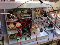
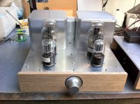
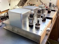
Here I'm back from an intensive weekend building the chassis and getting the different circuit blocks to work. Attached are some pictures of the current build. The 6sL7 driver has the PNP CCS board and the 45s have the Rod Coleman's DHT circuits.
Had some problems with my LT bench supply so ended up wiring an alternative supply that could cope with the heaters current demand...
Now have the pair of 45s regulating at 2.5V and 1.5A. Bias voltage at -45V but have some issues measuring the cathode current across an 1 ohm resistor which is connected from one filament to the HT ground bus. Without HT applied have some 10mV sensed across the resistor so I guess I have some leakage current across? I have emailed Rod to seek for some assistance...
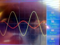
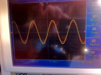
Either way, I did apply some input to the 6SL7 and got 160Vpp across the 45 anode with an 1.4vpp input. See my graphs attached, looks quite good and this should be about 2.5W across the 8ohm resistor?
Will keep working on it...
cheers,
Ale
Here I'm back from an intensive weekend building the chassis and getting the different circuit blocks to work. Attached are some pictures of the current build. The 6sL7 driver has the PNP CCS board and the 45s have the Rod Coleman's DHT circuits.
Had some problems with my LT bench supply so ended up wiring an alternative supply that could cope with the heaters current demand...
Now have the pair of 45s regulating at 2.5V and 1.5A. Bias voltage at -45V but have some issues measuring the cathode current across an 1 ohm resistor which is connected from one filament to the HT ground bus. Without HT applied have some 10mV sensed across the resistor so I guess I have some leakage current across? I have emailed Rod to seek for some assistance...
Either way, I did apply some input to the 6SL7 and got 160Vpp across the 45 anode with an 1.4vpp input. See my graphs attached, looks quite good and this should be about 2.5W across the 8ohm resistor?
Will keep working on it...
cheers,
Ale
Attachments
Modifying the driver circuit
Hi everyone,
Here I come again with an update. Have converted my valve rectifier to a hybrid one, so now my HT power supply can deliver 450V. This will definitely help me in fixing my driver circuit")
Have modified the 6SL7 driver circuit based on SY's CCS using the DN2540.
My constrain still is two octal sockets, so may change the valves if needed (e.g. 6SN7, 6BL7, etc), but these need to be a double triode in a single valve envelope
I have removed my paralleled 6SL7 and now have a 6SL7 grounded cathode biased at -2V (green LED) and 1.8mA and direct coupled to a cathode follower using the other half of the 6SL7 biased at 1.8mA as well. I suppose I can modify the bias point of the cathode follower, any recommedations?
With the current circuit the output impedance is around 660 ohms, the gain is 36.7dB (or 68.4), sensitivity is 5.4vpp delivering up to 374Vpp to the 45 output valve (I need 160vpp to deliver full SET power). Bandwidth is around 7Hz to 312kHz.
will you suggest changing the cathode follower to 6SN7 or 6BL7 to reduce further the output impedance? (these are the only double triode valves I have in octal envelope)
Many thanks for the help....
Cheers,
Ale
Hi everyone,
Here I come again with an update. Have converted my valve rectifier to a hybrid one, so now my HT power supply can deliver 450V. This will definitely help me in fixing my driver circuit
Have modified the 6SL7 driver circuit based on SY's CCS using the DN2540.
My constrain still is two octal sockets, so may change the valves if needed (e.g. 6SN7, 6BL7, etc), but these need to be a double triode in a single valve envelope
I have removed my paralleled 6SL7 and now have a 6SL7 grounded cathode biased at -2V (green LED) and 1.8mA and direct coupled to a cathode follower using the other half of the 6SL7 biased at 1.8mA as well. I suppose I can modify the bias point of the cathode follower, any recommedations?
With the current circuit the output impedance is around 660 ohms, the gain is 36.7dB (or 68.4), sensitivity is 5.4vpp delivering up to 374Vpp to the 45 output valve (I need 160vpp to deliver full SET power). Bandwidth is around 7Hz to 312kHz.
will you suggest changing the cathode follower to 6SN7 or 6BL7 to reduce further the output impedance? (these are the only double triode valves I have in octal envelope)
Many thanks for the help....
Cheers,
Ale
Attachments
Rod Coleman's board are working great. Input ripple is reduced from 760mVpp to less than 25mVpp. Input voltage is 9V and regulator is adjusted to 2.5V
Thanks Rod for the help to tune the LT supply and thanks Andy Evans for giving me a piece of that nice multicore cable!
Cheers
Ale
Thanks Rod for the help to tune the LT supply and thanks Andy Evans for giving me a piece of that nice multicore cable!
Cheers
Ale
An externally hosted image should be here but it was not working when we last tested it.
Hi Ale, Glad to see it's coming along!
Please take care with measurements and position of the 45s - many DHTs will behave strangely if operated at any angle away from the vertical. This is especially a risk in old DHTs, where the tension of the filaments may have slackened a little. In this case the filament-to-grid separation distance changes when running horizontally, and the anode current changes in a corresponding way! In the extreme, a short might occur.
I prefer to prop the amp up on four cans of beer to take measurements. When all the adjustments have been made, the four beers seem to improve the sound even further.
Do you have small values of capacitor on the filament raw dc? 760mV of incoming ripple seems high. With a CRC-connected supply of 10 000uF x2 and about 1R, it should be near to 250mV. This level should allow unmeasurably small ripple on the filament - much less than 1mV.
I bet it sounds good though....
Hi Rod,
Thanks, hard work but is slowly coming to life.
I'm using a circular 8-pole connector from Rapid to connect the two chassis and it seems it has a false contact that I lost the connection with the bias supply when I tested my HT supply. My HT voltage regulator obviously couldn't cope with the current load and I'm lucky that this one died and nothing happened to my 45 valves. Now I added a fuse and a HT switch, but still need to review what is going on with these connectors.
Thanks for the testing tips, will change my test layout then!
RE the ripple, have a look at the attached diagram. I have a couple of 15mF capacitors between the 0.47R resistor....
Cheers,
Ale
Attachments
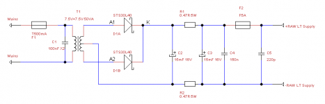
Ale, raw supply looks perfect.
Was the measurement taken while the HT was energised, or with only the filament ON?
With the values you have there, the ripple should be 150mV or so in the raw dc, and <<1mV across the filament - ie nothing should be visible if a scope is connected, and the most sensistive mV range selected.
Was the measurement taken while the HT was energised, or with only the filament ON?
With the values you have there, the ripple should be 150mV or so in the raw dc, and <<1mV across the filament - ie nothing should be visible if a scope is connected, and the most sensistive mV range selected.
Without HT is best, since HT noise couples into the scope.
It's sometimes hard to avoid measurement errors with a scope, especially if the probe's ground clip has long wire. Taking some bare, solid tinned copper wire [about 0.8mm dia or so] and wind around the probe ground band [clip removed]. Slide it off the probe and solder to the filament terminal [usually F+] that is connected to HT GND. Slide the probe back in, and solder a short wire to the other Filament terminal.
Long wires can pick up HF/UHF noise. This can be a problem if you live near big radio stations, Underground trains, trams, industrial works etc. If the noise is still evident with short probe wires, investigating some ferrite chokes and/or common-mode chokes can be very worthwhile for the sound quality. Use them in the HT supply and the filament supply.
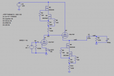
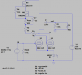
Slowly more progress on the amp. Have tweaked the driver stage as per attached.
Mosfet CCS. Va=260V and HT=350V. Got bias at around -1.8V with a yellow LED. Haven't measured Ia, but from anode curves and ltspice should be around 3.5mA.
When measured distortion got 0.12% @ 2.8Vpp and 0.04%@1Vpp.
I know that Thomas would say that is far from being and optimal driver, but it doesn't perform bad at all. Final judge would be the listening test and see how will respond to dynamics, which it may be the downside of running the valves cooler at 3.5mA.
Options I think I have is to aim for Vg=-2V (Red LED) Ia=5mA so will need to raise HT to 400V or look for an alternative driver i.e. 6N7 as suggested earlier and add a pre-amp stage (which I'm keen to build soon).
I will complete the build as is, so can listen to the results before changing this.
Any recommendations on the driver options or further tweaking the current one?
Many thanks
Ale
Attachments
Well, managed to do a quick end to end test and it sounds brilliant!
Output valves are running at 33mA and 300V as suggested by Kevin Maier
No hum at all, just used my Grado headphones and played a bit of Charlie Mingus, nice!
Good bass response, clear tone and warm sound...
Those Rod Coleman's regulators are supreme. No AC hum at all could be noticed, so quiet. Will measure the output levels when I get the chance...
More than 6 months on this... happy to see some results coming up finally!
Cheers,
Ale
You are right, but his music is brilliant
Still need to finish the amp to enjoy it with my full range speakers!
Didn't used the beer cans as Rod suggested, just put the amp upside down at the edge of the table, at least the valves are not horizontal though...
Still need to finish the amp to enjoy it with my full range speakers!
Didn't used the beer cans as Rod suggested, just put the amp upside down at the edge of the table, at least the valves are not horizontal though...
An externally hosted image should be here but it was not working when we last tested it.
Mogliaa, no hum with Grados is quite an accomplishment with a DHT amp, folks pay thousands and thousands of dollars for commercial DHT headamps without hum.
I was all set to use my set of coleman boards but the recommendation that they have to be in the same chassis as the tubes and fed from a separate umbilical cord than B+ had me delay the project. Who wants 2 umbilical cords ?
Can you explain how you accomplished the 2 chassis scheme using the colemen regs, i.e. board placement, tranny, cable used, etc.
thanks
Mogliaa, no hum with Grados is quite an accomplishment with a DHT amp, folks pay thousands and thousands of dollars for commercial DHT headamps without hum.
I was all set to use my set of coleman boards but the recommendation that they have to be in the same chassis as the tubes and fed from a separate umbilical cord than B+ had me delay the project. Who wants 2 umbilical cords ?
Can you explain how you accomplished the 2 chassis scheme using the colemen regs, i.e. board placement, tranny, cable used, etc.
thanks
I ended up with three chassis as I ran out of space on the HT chassis
HT chassis has also the bias supply and 8 core cable to the main chassis.
LT supply chassis is housing two e-core trannies for the 45s and one toroidal trannie I had at hand for the driver filament supply. On this chassis I have three raw supply boards and another multipole connector with 4 core cable from this chassis to the main one.
Now need to do the final assembly before I can test this amp with my Fostex 167 full range speakers!
Cheers,
Ale
- Status
- This old topic is closed. If you want to reopen this topic, contact a moderator using the "Report Post" button.
- Home
- Amplifiers
- Tubes / Valves
- Back at the 45 SET