Hi regal,
I don't know the regulator you intend to use. Be aware that it will be in the signal path and contribute it's own sonic character to the overall sound. Especially if the reg is at it's limit and on the verge of beeing stressed this could worsen the sound.
I've never liked SS regulated tube amps. But many people do. I prefer to stick with pure simple tube circuits. I prefer a good quality cap over a regulator (tube or SS) in the signal path.
Best regards
Thomas
I've never liked SS regulated tube amps. But many people do. I prefer to stick with pure simple tube circuits. I prefer a good quality cap over a regulator (tube or SS) in the signal path.
You have not heard the SSHV (Simplistic HV Shunt Regulator)... born and developped here on diyaudio (Salas is the originator).
I have two of them running in headphone amps, and they beat a conventional psu by a good margin. Sonically they retain all of the tube character
")
Hi!
No, I haven't, at least not that I'm aware of. But I did hear many SS regulated amps with various regulater topologies. Never came across one that I liked. But as I wrote other people do like that sound. Tastes and preferences are different
Best regards
Thomas
You have not heard the SSHV (Simplistic HV Shunt Regulator)... born and developped here on diyaudio (Salas is the originator)
No, I haven't, at least not that I'm aware of. But I did hear many SS regulated amps with various regulater topologies. Never came across one that I liked. But as I wrote other people do like that sound. Tastes and preferences are different
Best regards
Thomas
Hi!
one more comment
To put that in perspective it would be good to understand what you mean by conventional PSU. Tube rectified, choke input filter or cap input? Quality of caps used, etc. Many 'conventional PSUs' are quite compromised.
Best regards
Thomas
one more comment
I have two of them running in headphone amps, and they beat a conventional psu by a good margin. Sonically they retain all of the tube character
To put that in perspective it would be good to understand what you mean by conventional PSU. Tube rectified, choke input filter or cap input? Quality of caps used, etc. Many 'conventional PSUs' are quite compromised.
Best regards
Thomas
Hi!
No, I haven't, at least not that I'm aware of. But I did hear many SS regulated amps with various regulater topologies. Never came across one that I liked. But as I wrote other people do like that sound. Tastes and preferences are different
Best regards
Thomas
I hadn't heard a SS regulator I liked with SET until the Salas and it is an amazing piece of work, it give a low output impedance B+ that no conventional filtered B+ can offer. I'm surprised it hasn't been tried with a 45 yet.
My perspective: tube rectified (5R4), cap input (MKP) CLCRC or choke input LCRC. I also like to use ERO KP caps to bypass bigger values of MKP (I know, another No-No). The Salas shunt retains the body and warmth, but has more detail, is faster and has better soundstaging. YMMV
Hi Kevin,Driver actually isn't SRPP as connected, but mediocre current source loaded common cathode stage.. I think the cathode bias resistors in your SRPP are rather low in value, and I've found the 6SL7 to work best at currents of 2mA or less.. I'd recommend 820 - 1K resistors instead and I'd use it as an SRPP... The cathode bypass cap is a bit on the small side. A red led for bias on the bottom tube cathode and a 1K resistor in the top might make an interesting experiment.. (Section to section match could be an issue, and voltage will not divide evenly between the upper and lower sections of the SRPP - whether or not this is an issue depends on how extreme the imbalance is.)
Elevating the filament supply is really easy, it just takes 2 resistors and a cap and can be fed by your B+.. I would aim for more like 250V B+ and note that you can easily get 2Wrms out of this design with a 5K transformer, and that generally will translate into even better linearity at low levels than your current design. (4% thd at 2W is attainable with this tube.)
I strongly favor fixed bias and your OP is in the right range..
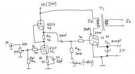
I have followed your advice and tweak the circuit accordingly. I now have the 45 operating at 33mA/244V using a 5K primary winding and can get 840mW at 2.2% THD from an input grid signal of 35V.
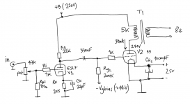
Now I have to driver options: an SRPP (option 1) and a simple cathode ground (option 2)
The symmetrical SRPP has of course better gain, less distortion and better PSRR. This configuration runs at 1mA and has a gain of 47.5
The common cathode circuit also is running at 1mA but gain is 22 - enough for what I need to drive the 45 SET I think. Of course the PSRR is worse and the output impedance is slightly higher than the SRPP - 14K against 12K
Is it worth implementing an SRPP in this configuration? Is the improvement in distortion that significant compared to the other option?
Should I try to add a CCS to the simple ground cathode circuit to get a bit of more headroom and better PSRR?
Thanks for the help - I'm really new to valve circuits....
Cheers,
Ale
Attachments
Hi Ale,
I think your circuit is unnecessarily complex. I don't see any advantage of the SRPP. It only brings problems with kathode-heater voltage differences and the need to elevate heaters. I played around with SRPP and mu followers a long time ago but dismissed them. I prefer transformercoupling, or if on a budget plain RC coupling.
I have mentioned in another thread that I think the 6SL7 is not well suited as a driver. if you insist on it, parallel both sections and run it RC coupled. Better choice is trhe 6N7 as mentioned by me earlier in this thread.
If you have the possibility for higher B+, use cathode bias on the 45. Way simpled than fixed bias.
Other points:
Why the huge grid stop resistor on the 6SL7? I've never experienced oscillations with the 6SL7, no grid resistor needed at all. Also the 45 will run fine without the grid stop resistor.
Best regards
Thomas
Hi Thomas,
Thanks for your help. Why would you use a 6n7 instead of a 6sl7? The 6sl7 has good gain.
I have many 27 I wanted to use but given the low mu, I don't think I can use them with my current design. I'm keen to see whether using SRPP has a significant advantage that is worth adding the extra complexity in the circuit...
Grid stopper is suggested in the tubecad design, do you suggest removing it?
Cheers,
Ale
Last edited:
Hi!
22k is way too low for a plate resistor for the 6SL7. The SRPP stage probably has the 13k ouptut impedance on paper. But running at 1mA it cannot really deliver a lot of power to the 45 grid.
While the 45 is fairly easy to drive it is advisable to drive with more guts than the 6SL7 can deliver. gain is not everything. A transformer coupled 6N7 stage will have about the same gain as a 6SL7 SRPP. For RC coupling it would be better to have higher B+ for the 6N7 (about 400V)
I used the 6N7 transformercoupled to drive the 45. This works nicely with Lundahl 1660/10mA.
SRPP circuts are know for their very load dependent distortion behaviour. Also the difference in heater-cathode voltage can cause the tubes to turn microphonic after a short while.
But best experience is to built different versions and listen to them.
About the grid stoppers: yes no need for them 6SL7 has low transcond8uctance and does not tend to oscillate. I built quite a few 45 amps, never used a grid stopper.
Thomas
I used the 6N7 transformercoupled to drive the 45. This works nicely with Lundahl 1660/10mA.
Hi Thomas,
Are you direct or parafeed coupling the N7? I'd be very interested in seeing your circuit if you don't mind sharing. I'm planning on building a SE 45 amp soon and am currently evaluating the numerous driver circuits out there.
Hi Thomas,
Again thanks for your time. I reset the 6SL7 anode current to 1mA due to Kevin's advice.
I will have to keep the circuit to an RC coupling at this point, so I'm keen to work around this configuration. Power supply also will be set to 250V if possible to avoid additional circuitry.
Will go for the simple grounded cathode driver then.
What is the current sunk by the output stage? If the miller capacitance is (a+1)*cg=28pF with a gain of 3 approx, then is pretty insignificant since the impedance at 10kHz will be about 560K (if I'm not mistaken) so the only significant load to the driver is the 200K bias resistor through the coupling capacitor of course, correct?
That is probably 100uA of sink/source from the driver. Have I done things wrong here?
How can you determine that the 6SL7 operated at 1mA is not sufficient to deliver the output power required by the 45 stage?
I haven't done this type of analysis for more than 10 years so apologies if I've made a massive mistake or assumption
cheers,
ale
Hi!
I used it with transformercoupling (no parafeed) with uktrapath cap and RC coupled. I first used the 6N7 as driver in a SE 6CB5A amp. Then build various amps employing the same driver (45, 2a3, 801A).
I will open a thread with the schematic of that 6CB5A amp.
Best regards
Thomas
Are you direct or parafeed coupling the N7? I'd be very interested in seeing your circuit if you don't mind sharing. I'm planning on building a SE 45 amp soon and am currently evaluating the numerous driver circuits out there.
I used it with transformercoupling (no parafeed) with uktrapath cap and RC coupled. I first used the 6N7 as driver in a SE 6CB5A amp. Then build various amps employing the same driver (45, 2a3, 801A).
I will open a thread with the schematic of that 6CB5A amp.
Best regards
Thomas
Hi!
I didn't imply hat it is insufficient, just that there are better choices IMHO. The 6SL7 will work. A grid, especially of a power tube is not a linear impedance. As it is excited it can show various non linearities due to grid current. A good design has a driver which is not heavily impacted by such effects.
I also prefer to have a driver with lots of headroom. The 6SL7 will have minimal headroom and thus contribute significantly to the distortion spectrum of the amp.
These are the typical designs which tend to change their sound character a lot if you do small changes in op point and B+. These are then often falsly attributed to the op point, B+ level, or even the rectifier tubes.
As suggested, if you stick with 6SL7 parallel two sections of the 6SL7 and run 2mA through them.
Best regards
Thomas
How can you determine that the 6SL7 operated at 1mA is not sufficient to deliver the output power required by the 45 stage?
I didn't imply hat it is insufficient, just that there are better choices IMHO. The 6SL7 will work. A grid, especially of a power tube is not a linear impedance. As it is excited it can show various non linearities due to grid current. A good design has a driver which is not heavily impacted by such effects.
I also prefer to have a driver with lots of headroom. The 6SL7 will have minimal headroom and thus contribute significantly to the distortion spectrum of the amp.
These are the typical designs which tend to change their sound character a lot if you do small changes in op point and B+. These are then often falsly attributed to the op point, B+ level, or even the rectifier tubes.
As suggested, if you stick with 6SL7 parallel two sections of the 6SL7 and run 2mA through them.
Best regards
Thomas
Hi!
I didn't imply hat it is insufficient, just that there are better choices IMHO. The 6SL7 will work. A grid, especially of a power tube is not a linear impedance. As it is excited it can show various non linearities due to grid current. A good design has a driver which is not heavily impacted by such effects.
I also prefer to have a driver with lots of headroom. The 6SL7 will have minimal headroom and thus contribute significantly to the distortion spectrum of the amp.
<snip>
As suggested, if you stick with 6SL7 parallel two sections of the 6SL7 and run 2mA through them.
Best regards
Thomas
I actually designed a 45 SE amp about 12yrs ago with a 6SL7 based SRPP driver running at 2mA.. This seemed to have sufficient drive to achieve a full power bandwidth in excess of 30kHz at the grid, and a peak to peak swing in excess of 110Vpp on a 320V supply which seemed sufficient at the time.. On a 250V supply I agree it might be a bit marginal, I am less a fan of paralleled triodes than I am of the SRPP.. Use separate cathode bias resistors for each section if you do parallel them as this will assure that both sections bias properly even if not particularly well matched.
Today I would do it with a choke loaded 5842/417A running at 15 - 20mA and 200V, plenty of headroom and lots of bandwidth.
Last edited:
I actually designed a 45 SE amp about 12yrs ago with a 6SL7 based SRPP driver running at 2mA.. This seemed to have sufficient drive to achieve a full power bandwidth in excess of 30kHz at the grid, and a peak to peak swing in excess of 110Vpp on a 320V supply which seemed sufficient at the time.. On a 250V supply I agree it might be a bit marginal, I am less a fan of paralleled triodes than I am of the SRPP.. Use separate cathode bias resistors for each section if you do parallel them as this will assure that both sections bias properly even if not particularly well matched.
Today I would do it with a choke loaded 5842/417A running at 15 - 20mA and 200V, plenty of headroom and lots of bandwidth.
Hi Kevin,
Thanks, seems there are multiple views
I may need to consider increasing the power supply to 300-350V and operating the 6SL7 at 2mA. May strap two in parallel as per previous suggestions with split cathode bias as you recommend. I guess that I will breadboard both options and see how they sound....
Will a CCS load have any improvement in the sound other than providing more headroom?
thanks
Ale
Hhi!
Yes, that's what I always say, there are different ways to reach good sound. There are different tastes...
That's why I encourage to actually try and listen for yourself.
I did that years ago and dismissed SRPP and similar schemes.
For me I ended up with higher power drivers and plenty of headroom.
BTW the 6N7 dirver is my choice for designs on a budget. They offer a good compromise of driver capability, headroom and cost. For 'ultimate' amps I'd use different tubes...
Best regards
Thomas
seems there are multiple views
Yes, that's what I always say, there are different ways to reach good sound. There are different tastes...
That's why I encourage to actually try and listen for yourself.
I did that years ago and dismissed SRPP and similar schemes.
For me I ended up with higher power drivers and plenty of headroom.
BTW the 6N7 dirver is my choice for designs on a budget. They offer a good compromise of driver capability, headroom and cost. For 'ultimate' amps I'd use different tubes...
Best regards
Thomas
Hi!
Maybe we have different views about headroom. I don't consider the 417A type tubes a good choice for a driver because it lacks headroom in this application IMHO.
What I consider as headroom: The amount of output voltage which a driver can deliver in excess of what is needed to drive the output tube to full power. Also it should have a bias voltage which is way above the maximum amplitude the amp can see at it's input.
I consider 6dB of headroom as adequate. In my own designs I shoot for 12 dB of headroom or more. 12dB headroom means:
- if the output tube needs 100V pp for full power, the driver can deliver 400V pp
- if the maximum amplitude on the input is 2V, the bias voltage of the driver is 8V
Best regards
Thomas
Today I would do it with a choke loaded 5842/417A running at 15 - 20mA and 200V, plenty of headroom and lots of bandwidth.
Maybe we have different views about headroom. I don't consider the 417A type tubes a good choice for a driver because it lacks headroom in this application IMHO.
What I consider as headroom: The amount of output voltage which a driver can deliver in excess of what is needed to drive the output tube to full power. Also it should have a bias voltage which is way above the maximum amplitude the amp can see at it's input.
I consider 6dB of headroom as adequate. In my own designs I shoot for 12 dB of headroom or more. 12dB headroom means:
- if the output tube needs 100V pp for full power, the driver can deliver 400V pp
- if the maximum amplitude on the input is 2V, the bias voltage of the driver is 8V
Best regards
Thomas
Hhi!
Yes, that's what I always say, there are different ways to reach good sound. There are different tastes...
That's why I encourage to actually try and listen for yourself.
I did that years ago and dismissed SRPP and similar schemes.
For me I ended up with higher power drivers and plenty of headroom.
BTW the 6N7 dirver is my choice for designs on a budget. They offer a good compromise of driver capability, headroom and cost. For 'ultimate' amps I'd use different tubes...
Best regards
Thomas
Yes, well you are right indeed. I will do some test and let you know how it sounds. Now that is Christmas time I have some time to work on this belated project
BTW, I have only one 6N7GT in stock. I do believe as well is a great valve. I have ordered some russian equivalents (6H7C) so will do some other tests later when they arrive...
cheers,
ale
45SET: 6SL7 driver CCS
Hi everyone,
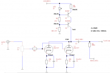
After some time I'm back on the 45SET project. I breadboarded the circuit with two paralleled 6SL7 driver using a resistor anode load and coupled to the 45 via a capacitor. Good results so far, so I spent most of my time building the chassis.
Now, after seeing the 4PL1 post from Wavebourn, I was encouraged to replace the anode resistor with a transistor CCS. Was keen to get into a mosfet gyrator, but I guess I needed to try a simple CCS to see the results.
I did a first FFT simulation with LTspice and got around 1.6% THD with the resistor load. I only considered the second harmonic for simplicity. I then replaced the anode resistor with the CCS as in the attached diagram. I got around 0.1%THD if my calculations are ok.
Before moving forward and build the final circuit, does anyone have any recommendations to this setup? Will it be worth pursuing a mosfet gyrator instead of a CCS?
Any suggestions are more than welcomed and thanks for your time.
Cheers,
Ale
Hi everyone,
After some time I'm back on the 45SET project. I breadboarded the circuit with two paralleled 6SL7 driver using a resistor anode load and coupled to the 45 via a capacitor. Good results so far, so I spent most of my time building the chassis.
Now, after seeing the 4PL1 post from Wavebourn, I was encouraged to replace the anode resistor with a transistor CCS. Was keen to get into a mosfet gyrator, but I guess I needed to try a simple CCS to see the results.
I did a first FFT simulation with LTspice and got around 1.6% THD with the resistor load. I only considered the second harmonic for simplicity. I then replaced the anode resistor with the CCS as in the attached diagram. I got around 0.1%THD if my calculations are ok.
Before moving forward and build the final circuit, does anyone have any recommendations to this setup? Will it be worth pursuing a mosfet gyrator instead of a CCS?
Any suggestions are more than welcomed and thanks for your time.
Cheers,
Ale
Attachments
- Status
- This old topic is closed. If you want to reopen this topic, contact a moderator using the "Report Post" button.
- Home
- Amplifiers
- Tubes / Valves
- Back at the 45 SET