Hi everyone,
After some time I'm back on the 45SET project. I breadboarded the circuit with two paralleled 6SL7 driver using a resistor anode load and coupled to the 45 via a capacitor. Good results so far, so I spent most of my time building the chassis.
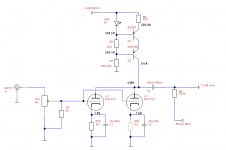
Now, after seeing the 4PL1 post from Wavebourn, I was encouraged to replace the anode resistor with a transistor CCS. Was keen to get into a mosfet gyrator, but I guess I needed to try a simple CCS to see the results.
I did a first FFT simulation with LTspice and got around 1.6% THD with the resistor load. I only considered the second harmonic for simplicity. I then replaced the anode resistor with the CCS as in the attached diagram. I got around 0.1%THD if my calculations are ok.
Before moving forward and build the final circuit, does anyone have any recommendations to this setup? Will it be worth pursuing a mosfet gyrator instead of a CCS?
Any suggestions are more than welcomed and thanks for your time.
Cheers,
Ale
Hi,
I've never experimented with the SS/CCS but what I would be interested in hearing what the A/B listening results are between the two - that is, done on the breadboard if that's practical.
From what you said you are just a step away from hearing the two side by side on the breadboard, correct?
I'm emphasizing the in-circuit test because simulators, while very handy, may not give a bottom line indicator of the actual differences in the sonic impression each approach might give. Setting the two side by side on the breadboard would seem to get to the heart of the matter very quickly.
Hi mogliaa,
The way your driver stage is set up with just 500mV bias it not only has zero headroom, it is not even able to drive the 45 to full power. The driver stage will dominate the sound of the amp like this.
Also why the 1k series resistor to the 6SL7 grids? 6SL7s are not prone to oscillations. If you still want to apply grid stoppers, you should put one in series with each of the grid. But I'd skip it completely.
It would also be a good idea to put a resisto to ground after the wiper of the pot. If the pot looses contact the grids still have a reference to ground. Something like 1Meg would be ok.
Best regards ... Thomas
Any suggestions are more than welcomed and thanks for your time.
The way your driver stage is set up with just 500mV bias it not only has zero headroom, it is not even able to drive the 45 to full power. The driver stage will dominate the sound of the amp like this.
Also why the 1k series resistor to the 6SL7 grids? 6SL7s are not prone to oscillations. If you still want to apply grid stoppers, you should put one in series with each of the grid. But I'd skip it completely.
It would also be a good idea to put a resisto to ground after the wiper of the pot. If the pot looses contact the grids still have a reference to ground. Something like 1Meg would be ok.
Best regards ... Thomas
Thanks Thomas,Hi mogliaa,
The way your driver stage is set up with just 500mV bias it not only has zero headroom, it is not even able to drive the 45 to full power. The driver stage will dominate the sound of the amp like this.
Also why the 1k series resistor to the 6SL7 grids? 6SL7s are not prone to oscillations. If you still want to apply grid stoppers, you should put one in series with each of the grid. But I'd skip it completely.
It would also be a good idea to put a resisto to ground after the wiper of the pot. If the pot looses contact the grids still have a reference to ground. Something like 1Meg would be ok.
Best regards ... Thomas
Well spotted. When I split the cathode resistor in two as per suggestion above, I made the stupid mistake of halving the value (400 ohms) rather than doubling it!
Why not grid stoppers? Isn't it a general rule to add stoppers to all valves?
I previously had a 220K grid leak resistor after the pot which I removed due to suggestions from other members of the forum. Agree that doesn't have the effect of grid leak as there is a 47K pot as well, but understand your point so will add the 1M resistor....
Thanks
Ale
Hi!
Many designs even use stupidly high value grid stoppers. And others again copy it. This way poor design practices get spread.
As you drew it, it wouödn't make sense anyways since grod stoppers need to be placed right at the grid pin. Usually 200-300 Ohms are enough. But I never saw oscilaltion problems with a 6SL7.
Thomas
So what is your op point now?I made the stupid mistake of halving the value (400 ohms) rather than doubling it!
They are required for high transconductance tubes since these are prone to oscillation. Many people just blindly copy them so it appears as a general rule.Why not grid stoppers? Isn't it a general rule to add stoppers to all valves?
Many designs even use stupidly high value grid stoppers. And others again copy it. This way poor design practices get spread.
As you drew it, it wouödn't make sense anyways since grod stoppers need to be placed right at the grid pin. Usually 200-300 Ohms are enough. But I never saw oscilaltion problems with a 6SL7.
Thomas
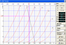
I changed the cathode resistor value to 600 ohms after running simulation with TubeCAD. I then run the simulation in LTspice which led to a 2.5mA anode current per valve and a anode voltage of 210V. Bias voltage is around 1.5V on each valve.Hi!
So what is your op point now?
Thomas
When I compare this result with the anode curves, I was expecting to match the 1.5V curve at 2.5mA and 245V, but it looks more closely to the 2V grid curve instead. The resistor load line is the equivalent since I cannot add a flat load line to represent the CCS.
What do you think about this operating point? I believe that gives sufficient headroom for a 2Vpp signal, doesn't it?
Thanks for the help
Ale
Attachments
Hi!
Better, but for my taste still not really good. Grid current effects and associated non linearities will start to kick in at bias voltages below -1V. I try to stay clear of this region in my designs. Simulation will not show you this.
Also you have more headroom at the 6SL7 input now. But with the B+ at 300V and plate voltage at 245V, not much headroom for the plate going positive.
I think I mentioned before that I don't think the 6SL7 is well suited for a driver tube.
Thomas
What do you think about this operating point? I believe that gives sufficient headroom for a 2Vpp signal, doesn't it?
Better, but for my taste still not really good. Grid current effects and associated non linearities will start to kick in at bias voltages below -1V. I try to stay clear of this region in my designs. Simulation will not show you this.
Also you have more headroom at the 6SL7 input now. But with the B+ at 300V and plate voltage at 245V, not much headroom for the plate going positive.
I think I mentioned before that I don't think the 6SL7 is well suited for a driver tube.
Thomas
Hi!
Better, but for my taste still not really good. Grid current effects and associated non linearities will start to kick in at bias voltages below -1V. I try to stay clear of this region in my designs. Simulation will not show you this.
Also you have more headroom at the 6SL7 input now. But with the B+ at 300V and plate voltage at 245V, not much headroom for the plate going positive.
I think I mentioned before that I don't think the 6SL7 is well suited for a driver tube.
Thomas
My 45 SET need 35Vpp on full power. So yet have a bit of headroom, agree that is not too much, but suits the requirements. What bias point would you recommend?
I have managed to get a couple of 6H7C (russian 6N7 equivalent), will you recommend using one of these with paralleled anodes instead?
Thanks
Ale
Hi!
35Vpp ? That would be quite low. Your bias voltage is indicated as 45V which would require 90Vpp normally. My own 45 even needs more than 100Vpp
Thomas
Hi Thomas.
You are quite right. I quoted 35vpp which was the calculated value for headphones output power. I need about 80vpp to get more than 1W
with the current bias point of 2.5mA per valve and anode voltage of around 245V set by CCS then I can get around 80Vpp with an input of 1.6vpp thus an output power of about 1.1W which is not bad....
45 bias point is Ia=32ma and Va=246V
Do you recommend changing to a 6N7 instead of the 6SL7?
thanks
ale
Hi!
I've written before that I like the 6N7 as driver. But you cannot just change the tube without adapting the circuit if you want optimum results. Unless you have substantial higher B+ for the driver (about 450V). You would need to either choke load the 6N7 or transformer couple it. inductive loading allows larger voltage swings at given B+ compared to resitor or CCS loading
Best regards ... Thomas
Do you recommend changing to a 6N7 instead of
I've written before that I like the 6N7 as driver. But you cannot just change the tube without adapting the circuit if you want optimum results. Unless you have substantial higher B+ for the driver (about 450V). You would need to either choke load the 6N7 or transformer couple it. inductive loading allows larger voltage swings at given B+ compared to resitor or CCS loading
Best regards ... Thomas
nothing wrong with 6v6 in triode mode.
Wavebourn recommended 4p1l in triode strapped being more linear than 2a3. What was your experience with 6v6 triode strapped?
I have some 45 NOS I'm currently testing, but I'm keen to test other options as well
Cheers,
Ale
Are there any inexpensive #45 tubes left?
They are getting to be around $60 and up NOS.
I recall seeing RCA Globe pairs fetching $250 3+ years ago and good ST pairs seeing $150 and more depending on brand, condition and matching.
I prefer ST glass over the original Globe type. By comparison, the globes have the highest measured distortion, the lowest signal-to-noise and are extremely sensitive to any mechanical excitation. It doesn't take much to set them off.
Even in ST glass, I prefer a specific internal construction which is older Sylvania and I have some identical internals branded as Philco, Zenith and Ken-Rad. My least favorite are the RCAs. I also have some good performing tubes which are Tung-Sol and GE. The 45 is still may favorite DHT... I think every good DIYer should have a more than a few good pairs

Regards, KM
Ia= 5mA and Vg=-1.2V bias point for 6SL7 driver
Hi Thomas,
I guess I found a compromise bias point at -1.6V. This will give me 80Vpp output with a 1.2Vpp @5mA anode quiescent point. Also the grid voltage stays above below -1V as per you recommendation.
I should have a higher HT supply than 300V, but at the moment can't do.
I may add at a later stage the MOSFET follower included in the Tubelab design, but will try this first and see the results before changing this circuit.
Also, here is a picture of my work in progress 45SET amp...
Cheers,
Ale
45SET operating point:

Simulation:

Work in progress:

Hi!
Better, but for my taste still not really good. Grid current effects and associated non linearities will start to kick in at bias voltages below -1V. I try to stay clear of this region in my designs. Simulation will not show you this.
Also you have more headroom at the 6SL7 input now. But with the B+ at 300V and plate voltage at 245V, not much headroom for the plate going positive.
I think I mentioned before that I don't think the 6SL7 is well suited for a driver tube.
Thomas
Hi Thomas,
I guess I found a compromise bias point at -1.6V. This will give me 80Vpp output with a 1.2Vpp @5mA anode quiescent point. Also the grid voltage stays above below -1V as per you recommendation.
I should have a higher HT supply than 300V, but at the moment can't do.
I may add at a later stage the MOSFET follower included in the Tubelab design, but will try this first and see the results before changing this circuit.
Also, here is a picture of my work in progress 45SET amp...
Cheers,
Ale
45SET operating point:
Simulation:
Work in progress:
Also, here is a picture of my work in progress 45SET amp...
Cheers,
Ale
YUMMI!
 where did you get those transformer covers?
YUMMI!
Hi Gluca,
The transformer covers come from Shuguang,Shuguang treasure,Fullmusic,Guiguang tubes,amplifier chassis,tube sockets,capacitor,resistors,coil meters,toggle switches,tag boards,transformer covers,various parts for tube guitar amps diy <meta name="keywords" content="tube sockets,shugua
Cheers,
Ale
Last edited:
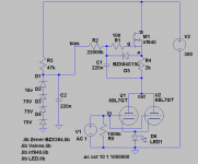
Mosfet CCS
Well, back to work on my 45 SET amp. I have enjoyed a long bank holiday weekend at the sun, but also managed to spend some time on my project...
After spending a bit of time simulating CCS options with ltspice, decided to etch a pcb for a mosfet CCS based on suggested designs in the forum. Since I had lots of IRF840, I used this mosfet for my CCS, although the quiescent current is only 4mA.
My first test was on Ia=5mA and Va=258V, which gave terrible results: Sensitivity only of 0.7vpp and Vo=46Vpp. Not enough driving voltage for the 45 valves. I know Vinylsavor predicted this, but didn't want to give up so easily and sought for a different operating point.
Second attempt on Ia=4mA and Va=236V. This was done after tweaking my zener network and bias current since 5mA was too much and reduced it to enable the zeners to regulate at 241V. So now the sensitivity increased to Vi=1.4Vpp and Vo=91.2Vpp before any second harmonic can be detected in my oscilloscope FFT. This looks good now! In my design I need 80Vpp to achieve 2W of output power, so I'm ok with this. I know this can be better achieved with greater supply voltage, but I'm limited to 300V at the moment.
A slight reduction in gain was the price to pay, buy I'm fine with Av=65.
Also did a quick frequency response test and got a flat response to 78kHz (-3dB) point.
What I noticed is that I couldn't change too much the current bias point of the 6SL7 pair by changing R4 - is a 100 ohm resistor with a 5K trimpot in series in my pcb.
Any view as to why this can be?
Any other recommendations before moving forward to the next stage?
Attachments
What I noticed is that I couldn't change too much the current bias point of the 6SL7 pair by changing R4 - is a 100 ohm resistor with a 5K trimpot in series in my pcb.
Any view as to why this can be?
That's because R4 is small compared to the internal resistance of the SL7. And the gate is DC referenced to the plate voltage. So changing it won't much change the voltage at the source.
Sheldon
- Status
- This old topic is closed. If you want to reopen this topic, contact a moderator using the "Report Post" button.
- Home
- Amplifiers
- Tubes / Valves
- Back at the 45 SET