This is where an adjustable current source in the drain of the driver FET might be useful. However, one would necessarily adjust it depending on the allowable grid current for each tube to be tested.
It would become another adjustment that if forgotten could result in a damage tube.
It would become another adjustment that if forgotten could result in a damage tube.
This is where an adjustable current source in the drain of the driver FET might be useful. However, one would necessarily adjust it depending on the allowable grid current for each tube to be tested.
It would become another adjustment that if forgotten could result in a damage tube.
More knobs!

Nothing new to report... but here are some shots I took today with and without power grid/RF interference, quite a big difference as you can see...
An externally hosted image should be here but it was not working when we last tested it.
An externally hosted image should be here but it was not working when we last tested it.
Jaz
Last edited:
Jaz,
Second trace looks really good. What is the difference between the two, just interference?
Have you tried removing the grid stopper or using 10/100 ohms? Lower value will definitely help specially if you are using a ferrite bead in the grid cable just right at the socket pin. If you are careful enough not to overheat the grid you will be able to see a proper curve for 0V grid bias.
There is an interesting thread about mains filtering opened this week. Have a look.
I added a mains filter classic common choke with X2 caps before and after. It has actually helped when the wife uses the microwave
What is your sensing circuit? I'm using a differential op amp arrangement to provide x1/x10 and inversion as well to be flexible for future analogue scopes I may end up with. The sensing cable from the sensing resistor to this amp should be shielded to avoid interference. Think when you are plotting low anode current valves.
Have you tried plotting power valves? Different beast btw...
Ale
Jaz,
Second trace looks really good. What is the difference between the two, just interference?
Have you tried removing the grid stopper or using 10/100 ohms? Lower value will definitely help specially if you are using a ferrite bead in the grid cable just right at the socket pin. If you are careful enough not to overheat the grid you will be able to see a proper curve for 0V grid bias.
There is an interesting thread about mains filtering opened this week. Have a look.
I added a mains filter classic common choke with X2 caps before and after. It has actually helped when the wife uses the microwave
What is your sensing circuit? I'm using a differential op amp arrangement to provide x1/x10 and inversion as well to be flexible for future analogue scopes I may end up with. The sensing cable from the sensing resistor to this amp should be shielded to avoid interference. Think when you are plotting low anode current valves.
Have you tried plotting power valves? Different beast btw...
Ale
Ale,
Nothing is different other than the time of day - during business hours, I get crazy interference, basically rendering the tracer useless.
I tried the line filter too, alas it's no use against such outrageous level of interference...BTW, the valve shown is a 5881/6L6 type triode-strapped and the vertical scale is 50mA/div. My plate transformer is already running out of juice, so I can't go much beyond 300V at the moment. All the cable for the sense lines are shielded, and ferrite beads are place close to the pins of the individual tube sockets. The grid stop resistors are selectable 100, 1K or 10K, but I need to move them closer to the tube pins when I re-do the layout. When there is no interference, I can almost get away with no stopper, with the darn interference, even 10k can't do anything...
Below is my current sense amp based on the INA128, with x10 or x50 gain, the sense resistor is selectable 1R or 10R:
An externally hosted image should be here but it was not working when we last tested it.
Jaz
Last edited:
Have you tried sensing just with a resistor to the return of the plate drive like in the tek570? Is the noise being injected to the Plate drive or to the grid drive? In my case when i have noise is just the plate drive.
One item that i added to mine is a momentary switch that grounds the grid of the DUT to give me a reference of the zero curve and adjust the bias level to match the top curve of the family of curves with it, same as Tek570.
One item that i added to mine is a momentary switch that grounds the grid of the DUT to give me a reference of the zero curve and adjust the bias level to match the top curve of the family of curves with it, same as Tek570.
Have you tried sensing just with a resistor to the return of the plate drive like in the tek570? Is the noise being injected to the Plate drive or to the grid drive? In my case when i have noise is just the plate drive.
One item that i added to mine is a momentary switch that grounds the grid of the DUT to give me a reference of the zero curve and adjust the bias level to match the top curve of the family of curves with it, same as Tek570.
I'm think it's coming from the plate drive as well, since the grid is very clean without the plate drive turned up. I think I tried the sense resistor on the return leg of the Plate Sweep earlier and it did not seem to make a difference, but many things have been changed since then, so I will take another look to see, thanks for the suggestion.
I think I will add the Zero Bias button, and the the Start Adjust pot as well, but as mentioned, I can't get the steps above zero - still more work to do. Do you have some shots of the grid drive with the positive steps when tracing curves? May be like:
An externally hosted image should be here but it was not working when we last tested it.
Jaz
Last edited:
Hi Jaz
I do have control in the positive area although I rarely use it. I use the bias level all the time to match against the zero curve.
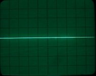
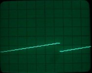
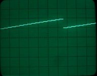
I have three pictures, the zero reference, one step family below zero and one above it. I do have individual control of step size an steps per family. Vertical is at 20V/division.
I also recorded a short video so you can see the operation.
link to short video
I do have control in the positive area although I rarely use it. I use the bias level all the time to match against the zero curve.
I have three pictures, the zero reference, one step family below zero and one above it. I do have individual control of step size an steps per family. Vertical is at 20V/division.
I also recorded a short video so you can see the operation.
link to short video
Attachments
Hi Jaz
I do have control in the positive area although I rarely use it. I use the bias level all the time to match against the zero curve.
I have three pictures, the zero reference, one step family below zero and one above it. I do have individual control of step size an steps per family. Vertical is at 20V/division.
I also recorded a short video so you can see the operation.
link to short video
Awesome, that's exactly how it should be.
Jaz
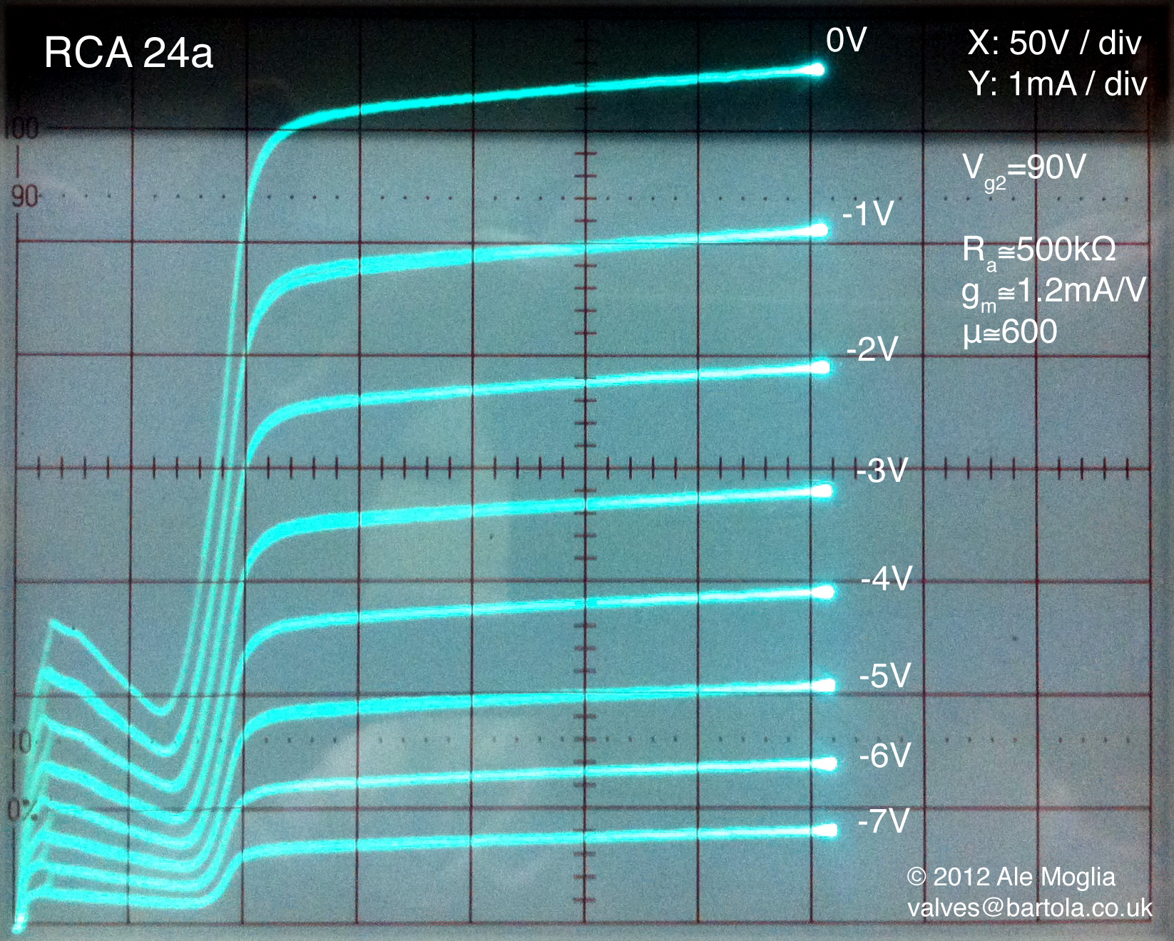
Built a simple source follower to provide screen bias. Here is a sample of a 24a tetrode with its characteristic kink:
http://www.bartola.co.uk/valves/2012/11/08/24a-tetrode-curves/
Cheers
Ale
http://www.bartola.co.uk/valves/2012/11/08/24a-tetrode-curves/
Cheers
Ale
Did not make too much progress this weekend, I tried a few different things but in the end, still not quite there...
Alfredo - I tried using a simple unregulated supply for the Vd and Vs for the FETs, like the ones used for your LME49810, but I end up with large ripples on the grid steps, so that's no go (the actual ripple on the supply line was pretty low). With the bench supply, the steps are ruler-flat, given the relatively low current for the grid drive, I still do not understand why it would be the case.
I now have spend more than a week trying to get the grid driver amplifier to work properly, for such a simple circuit, it sure gave me a lot of grief. Anyway, back to the breadboard...
Jaz
Alfredo - I tried using a simple unregulated supply for the Vd and Vs for the FETs, like the ones used for your LME49810, but I end up with large ripples on the grid steps, so that's no go (the actual ripple on the supply line was pretty low). With the bench supply, the steps are ruler-flat, given the relatively low current for the grid drive, I still do not understand why it would be the case.
I now have spend more than a week trying to get the grid driver amplifier to work properly, for such a simple circuit, it sure gave me a lot of grief.
Anyway, back to the breadboard...Jaz
Gents,
I am in the process of making v.2 of my tracer - need to improve the layout and the chassis. But I was thinking about another way to go about it and want to run it by you guys to see if it is feasible...
Here is the basic idea - use PC based scope and generator (which would eliminate many knobs and some real estate on the front/panel and controller board) and an external power amp to drive the grid. Like this:
Not very sophisticated, I know... but what do you think?
TIA,
Jaz
I am in the process of making v.2 of my tracer - need to improve the layout and the chassis. But I was thinking about another way to go about it and want to run it by you guys to see if it is feasible...
Here is the basic idea - use PC based scope and generator (which would eliminate many knobs and some real estate on the front/panel and controller board) and an external power amp to drive the grid. Like this:
An externally hosted image should be here but it was not working when we last tested it.
Not very sophisticated, I know... but what do you think?
TIA,
Jaz
why don't you guys just use a XY plotter instead ?
Hp made some 0-300v 100ma power supplies, use another 0-60v for bias purposes. add a heater supply and your all set
Heck, be course a Xy writer is tracking you could even use a unregulated supply for example just a mosfet source follower.
cheers, V4lve
Hp made some 0-300v 100ma power supplies, use another 0-60v for bias purposes. add a heater supply and your all set
Heck, be course a Xy writer is tracking you could even use a unregulated supply for example just a mosfet source follower.
cheers, V4lve
why don't you guys just use a XY plotter instead ?
Hp made some 0-300v 100ma power supplies, use another 0-60v for bias purposes. add a heater supply and your all set
Heck, be course a Xy writer is tracking you could even use a unregulated supply for example just a mosfet source follower.
cheers, V4lve
Have not seen a XY plotter for sale in ages... And the data is still on paper not in the PC (for creating Spice modesl and whatnot)...
Jaz
Jaz,
A different route that will bring its own challenges. Have a look at Yves design. He posted the link to his website earlier in this thread. His tracer is based on a PC. Also Michael Koster was working on a digital tracer as well. Not necessarily a simpler project.
When I first built it as a breadboard, there was no shielding, minimum ferrite beads and long cables. Despite this mess, it worked fine. My only challenge has always been keeping the sync due to the PLL stability. That is something it can be improved.
I will encourage you to continue looking at what may be not working for you as you are very close to the end goal now!
Ale
Jaz,
A different route that will bring its own challenges. Have a look at Yves design. He posted the link to his website earlier in this thread. His tracer is based on a PC. Also Michael Koster was working on a digital tracer as well. Not necessarily a simpler project.
When I first built it as a breadboard, there was no shielding, minimum ferrite beads and long cables. Despite this mess, it worked fine. My only challenge has always been keeping the sync due to the PLL stability. That is something it can be improved.
I will encourage you to continue looking at what may be not working for you as you are very close to the end goal now!
Ale
Ale,
I am still planning to complete v.2 of my manual curve tracer for sure. I tried Yves' program but could not make it run properly on my PC, but it looks very good from the pictures on his site...
Jaz
Have not seen a XY plotter for sale in ages... And the data is still on paper not in the PC (for creating Spice modesl and whatnot)...
Jaz
I have an HP7470 Plotter which is very easy to use -- if you know how to configure the serial port (a legacy art which is lost to the foggy mist of the ages for all I-Pad users.)
You can always take the data from paper and convert it to a table with a "grabber" program. I've done this for some ham radio tubes for which SPICE is non-existent, and you might have seen the equations i worked up for LDR's using this method.
Best of all, just get a little data-logger, they're less than $50.
No doubt the X-Y plotter and the data-logger would work fine, but I like to avoid the in-between steps as much as possible - so using PC based test software such as TureRTA, Visual Analyser, Daqarta, etc. might be a way to go. I am sure there are some issues to be sorted out, such as soundcard interface/buffer, line sync, etc. More things to try/play with...
Jaz
I finally completed the adapter... Thanks to Alfredo and Ale for the inspiration and assistance during the troubleshooting phase. I also made a new front panel to replace the beat-up one used in the previous version. I posted the results at DIY Valve Curve Tracer Adapter v.2 jazzbo8's adventure
Jaz
Jaz
- Status
- This old topic is closed. If you want to reopen this topic, contact a moderator using the "Report Post" button.
- Home
- Design & Build
- Equipment & Tools
- DIY Curve Tracer