Yes, very close") I have problems with ac noise as well, especially with my home HPNA network and the microwave. I think Ale used a filter on his unit.
I have problems with ac noise as well, especially with my home HPNA network and the microwave. I think Ale used a filter on his unit.
you must be tracing a small signal valve, what happens when you trace something with more plate current, it should clean up.
It appears as if there is some resistance affecting your current sensing circuit as the cutoff signal is not laying on top the zero current horizontal line.
I have problems with ac noise as well, especially with my home HPNA network and the microwave. I think Ale used a filter on his unit.you must be tracing a small signal valve, what happens when you trace something with more plate current, it should clean up.
It appears as if there is some resistance affecting your current sensing circuit as the cutoff signal is not laying on top the zero current horizontal line.
Yes, very close
you must be tracing a small signal valve, what happens when you trace something with more plate current, it should clean up.
It appears as if there is some resistance affecting your current sensing circuit as the cutoff signal is not laying on top the zero current horizontal line.
Good eyes! So far, I have only tried 12AX_ tubes and kept the plate voltage pretty low, based on your comment, I stuck in a 5881 and cranked it up, the curves were indeed much cleaner!
Here is the latest shot (5881):
An externally hosted image should be here but it was not working when we last tested it.
I still need to work on the volts/step, the grid bias circuit and of course the chassis as they are still not to my liking, but at least it is another step closer to completion.
Thanks,
Jaz
Jazz, looking good!
My advice is to try some different types of valves to see whether you may experience any oscillations or issues with your driving circuit. Just experiment more before moving into the final build stage. I used plenty of ferrite beads between sockets and also from grid and anode drivers to the test sockets
Ale
Looking good indeed!
I would also suggest some plate current limiting resistors. Not sure what the screen scale is but it appears the 5881 is passing some serious current near the top traces. The slope of the 0v trace is starting to slope down at the end. You dont want to cook the tube. Or it could just be your plate supply is running out of current to give.
Afredo
Remaining Issues
Thanks, guys! Couldn't have gotten this far without your guidance... I am still struggling with the grid drive circuit, the leftmost curve that you see in fact is not quite at Vg=0, since the circuit breaks into oscillation as Vg approaches zero let alone going above zero.
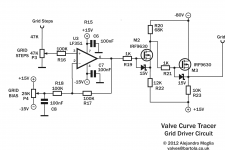
Ale, on your schematic, you showed the IRF9630's as two source followers, is that what you are using? In my version, the second 9630 is driven from the drain of the first 9630 instead, otherwise I could not get the swing required.
Alfred, I do have plate limiting resistors like the Tektronix (and your schematic), I just did not turn it up far enough when the shot was taken.
Here is the latest gate drive circuit (taken from one of drawings from TheGimp), it sims fine, but does not work as is in my setup...
TIA,
Jaz
Thanks, guys! Couldn't have gotten this far without your guidance... I am still struggling with the grid drive circuit, the leftmost curve that you see in fact is not quite at Vg=0, since the circuit breaks into oscillation as Vg approaches zero let alone going above zero.
Ale, on your schematic, you showed the IRF9630's as two source followers, is that what you are using? In my version, the second 9630 is driven from the drain of the first 9630 instead, otherwise I could not get the swing required.
Alfred, I do have plate limiting resistors like the Tektronix (and your schematic), I just did not turn it up far enough when the shot was taken.
Here is the latest gate drive circuit (taken from one of drawings from TheGimp), it sims fine, but does not work as is in my setup...
An externally hosted image should be here but it was not working when we last tested it.
TIA,
Jaz
Hi Jaz,
Here is the driver. I think I ended up adding a drain resistor in the output mosfet to protect it in case of grid shorts. Other than that, this works brilliantly for me...
Ale,
Thanks for posting the updated schematic, I will give it a try and report back, hope to have it sorted out soon, thanks again for your help.
Jaz
Ale,
I tried your values just now, and the result was the same... Vg=0 gets distorted when the grid current begins to flow. No problem with the small signal triodes since they don't draw much grid current (at least the ones I tried).
Also, even with 15V on the source, it still does not pull above 0, so no way to trace Vg>0, I'm still not sure why that would be the case, as the sim showed that it should be able to pull above 0.
With about 250V on the plates, here are some shots of the grid drive:
With 5881 (see the bow on the Vg=0 step):
https://dl.dropbox.com/u/1326040/IMG_1669_sm.jpg
with 12AX7 (clean Vg=0):
https://dl.dropbox.com/u/1326040/IMG_1674_sm.jpg
Thanks,
Jaz
Last edited:
I do see that your drawing shows the grid signal being taken from the Drain. Ale shows his on the Source. It probably makes a difference.
It is taken from the source, I just flipped the FET's on the drawing.
If I can get the LME49810 and an appropriate xfmr, I may give your version a try.Thanks,
Jaz
Oops didn't search enough:
http://www.ebay.com/itm/LME49810-200V-HiFi-Audio-Power-Amplifier-Driver-stage-Qty-1-/170825549153?pt=LH_DefaultDomain_0&hash=item27c5ff0561
less than eight with shipping
I plan on using one for my tracer if I ever get back to it.
http://www.ebay.com/itm/LME49810-200V-HiFi-Audio-Power-Amplifier-Driver-stage-Qty-1-/170825549153?pt=LH_DefaultDomain_0&hash=item27c5ff0561
less than eight with shipping
I plan on using one for my tracer if I ever get back to it.
Last edited:
Oops didn't search enough:
LME49810 200V HiFi Audio Power Amplifier Driver Stage Qty 1 | eBay
less than eight with shipping
I plan on using one for my tracer if I ever get back to it.
The LME49810 is about $4/ea. here in Shanghai, I am going to the surplus store to see if there is a suitable transformer first, if not, I will go with some back-to-back filament transformers that I have - looks like I won't have any room left in my so-called "chassis".
Jaz
Ale,
I tried your values just now, and the result was the same... Vg=0 gets distorted when the grid current begins to flow. No problem with the small signal triodes since they don't draw much grid current (at least the ones I tried).
Also, even with 15V on the source, it still does not pull above 0, so no way to trace Vg>0, I'm still not sure why that would be the case, as the sim showed that it should be able to pull above 0.
With about 250V on the plates, here are some shots of the grid drive:
With 5881 (see the bow on the Vg=0 step):
https://dl.dropbox.com/u/1326040/IMG_1669_sm.jpg
with 12AX7 (clean Vg=0):
https://dl.dropbox.com/u/1326040/IMG_1674_sm.jpg
Thanks,
Jaz
Hi Jaz,
Well, not sure what bias voltages you have on the FETs. Are u using same power supplies, 5 instead of 15V will make an impact and you will need to change the resistor values.
Looking at your first step is clearly sign of grid current. What grid stopper are u using? I have a switch to select from 0, 100 and 1k resistor I think. I do play with it when this is the case...
Ale
Ale,
Everything was the same as your drawing. The grid stopper was 1K, tried 10K as well - same result. As I already made a mess of the breadboard, I will re-do it again properly and see if the wiring/layout makes a difference.
Jaz
Me too!
Ale
Yes, I deleted it. I thought I had found a solution to the grid drive (pulling above zero), but it turned out to be short-lived. This was what happened, I did some tests with an IRF840 as the source follower and put +100V on its drain, -100V on its source via a 22K resistor. The waveform looked great without the TUT, when I plug it in and switched on the heater, then the top step got squashed again, anyway, now I can get a solid Vg=0 but not much above that, I don't understand what's happening, need to go back to the textbooks to see how the heater voltage affect the grid, why is it acting like a clamp on the positive grid voltage?
Will report back once I get a handle on it, or if you already know the answer, kindly share it with me. Thanks,
Jaz
I think what you're experiencing is a lot of grid current. When near 0V or above you will get current flowing through the grid and this creating a voltage drop across the grid resistor which will turn off the FET depending on the bias used.
I will try to remove the grid resistor - just ensure you have some protection on the drain of the output FET and see what you get.
Ale
I will try to remove the grid resistor - just ensure you have some protection on the drain of the output FET and see what you get.
Ale
Hi Jaz,
Simply because the grid/cathode space become a forward biased diode when a positive voltage is applied to the grid.
The grid becomes a small anode and "sink" some so called "grid current".
You may choose to build a beefy grid voltage generator with the risk to blow up the grid of a tinny tube.
The same problem will rise up when wou'll start playing with tetrodes and pentodes !
Yves.
Last edited:
Hi Yves,
I will let all it sink in. In the meantime, also found this:
Grid stoppers with AB2 which is relevant to the discussion, I think... It appears that I went overboard with the drain voltage and using a large NMOS like IRF840 probably isn't a good idea either (well that was what I had on hand), so I will try a smaller source follower at lower voltage and move the grid stop resistor closer to the gate (too far now with long wires). Getting there, slowly but surely...
Thanks,
Jaz
I will let all it sink in.
In the meantime, also found this:Grid stoppers with AB2 which is relevant to the discussion, I think... It appears that I went overboard with the drain voltage and using a large NMOS like IRF840 probably isn't a good idea either (well that was what I had on hand), so I will try a smaller source follower at lower voltage and move the grid stop resistor closer to the gate (too far now with long wires). Getting there, slowly but surely...
Thanks,
Jaz
- Status
- This old topic is closed. If you want to reopen this topic, contact a moderator using the "Report Post" button.
- Home
- Design & Build
- Equipment & Tools
- DIY Curve Tracer