Lets see what we can do. Bigun, how many exactly of which tubes do you have? Two or four 6AS7, driven by 6SN7 would make a sweet amp, but you will most likely have to roll a few to get a reasonably matched pair, also, 6SN7 is a great tube, only drawback being somewhat low gain for such an application, I'd get a 6SL7 (or a few, they are a handy tube) to drive the 6AS7's for the higher Voltage swing.
The 6AS7 has a Mu of only two, which makes it somewhat difficult to drive in a tube-stingy SE design, However, you could do a ccs loaded 6SL7 , with an LED in it's cathode, and have your 6AS7 biased about -60~70v (60mA or so through a 1k cathode R) and you should have a decent starting point.
The 6AS7 has a Mu of only two, which makes it somewhat difficult to drive in a tube-stingy SE design, However, you could do a ccs loaded 6SL7 , with an LED in it's cathode, and have your 6AS7 biased about -60~70v (60mA or so through a 1k cathode R) and you should have a decent starting point.
Member
Joined 2009
Paid Member
Hi Bigun;
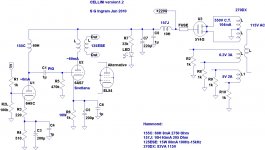
since you are fluent with SS, you may go directly to Gyrator load jumping over chokes.
Yes, I really like this approach and I looked at your particular version a few months back with the idea of using it as a load in a SS amp. Your gyrator is more than a gyrator, very interesting circuit. But my tube journey has to start at the beginning, without any semiconductors (except for the n-type semiconductor coating on the Cathode that is...). No reason why I can't try out a gyrator later.
275 x 1.4 = 385 V RAW DC less voltage drop across the rectifier, and the Rs & Ls in the series legs of the PSU filter.
dave
I guess I lose the factor of sqrt(2) in using a choke loaded psu. If I were using caps it would be a different story.
Lets see what we can do. Bigun, how many exactly of which tubes do you have? Two or four 6AS7, driven by 6SN7 would make a sweet amp, but you will most likely have to roll a few to get a reasonably matched pair, also, 6SN7 is a great tube, only drawback being somewhat low gain for such an application, I'd get a 6SL7 (or a few, they are a handy tube) to drive the 6AS7's for the higher Voltage swing.
The 6AS7 has a Mu of only two, which makes it somewhat difficult to drive in a tube-stingy SE design, However, you could do a ccs loaded 6SL7 , with an LED in it's cathode, and have your 6AS7 biased about -60~70v (60mA or so through a 1k cathode R) and you should have a decent starting point.
I expect to be receiving one 6AS7. That's not to say I can't obtain a second one but how would I use it ? This is really my first project and the power output is not a concern at this point (I want to avoid pushing the OT in order to get the best bandwidth from it). I want to start with SE not PP. But who's to say where this will lead when I come to build another

Now, with a choke load (from the OT) on the output tube I have something that is pretty close to a CCS do I not ? with the added benefit that the choke allows the plate voltage to go above B+ so that my limited rail voltage is less of a problem. Same goes for the input tube which I'm also now going to use a choke load for too.
GAIN
====
I understand that there isn't much gain here, but I'm not sure I need very much gain. With a choke load for the input tube I'm going to get a lot more gain. I'm actually concerned that I will have too much gain and I'm now showing an additional degeneration resistor in case this is necessary to bring the gain back down. It's something I'd like some advice on ?????
The input tube I have been given is apparently a nice one. It's actually a Russian 6H8C of some vintage. It comes in a very old looking unmarked box with a piece of paper inside testifying to the Russian military standards.
No C.T. on the heater secondaries so I guess I need to resistively couple them to gnd to reduce hum ?
I've shown a rail fuse in the schematic - a practice from my SS days, is this recommended for tubes ?
Attachments
Last edited:
That would most likely be a very acceptable amplifier as you've drawn it, like before though, you may not have enough gain for full output from most sources, most variations of 6SN7 driven 6AS7 SE that I have seen needed additional gain to reach full output, 6SN7 type tubes simply lack the amount of gain required. If it was me, I'd run a 6SL7 (or equivalent) and then implement a small amount of negative feedback into its cathode to tighten things up and eat some unneeded gain.
I say, build it, then tweak as needed. That's most of the fun in this hobby!
I say, build it, then tweak as needed. That's most of the fun in this hobby!
Member
Joined 2009
Paid Member
Member
Joined 2009
Paid Member
Thanks Lingwendil, I'll keep on trucking then !
Let me ask if my own understanding is correct here.
Gain of input stage is maximum with a CCS and no unbypassed cathode resistor. The gain is effectively equal to mu. With a choke load I am pretty much in CCS territory which means I can ignore the plate resistance ?
So my maximum gain is equal to mu, or around 21dB. I think this is enough gain for my application with the source I will be using (YBA CD player and Magnum Dynalab analogue FM).
Does this sound reasonable ?
Wavebourn - I believe you are saying I should not be using any resistors on the secondary for the rectifier heater, there is not a hum concern there and internally the rectifier has the cathode tied to the heater at one end anyhow.
p.s. my 6H8C is from 1957
p.p.s I have been given a nice bag of capacitors, Sprague Atom 20uF each 500V rated
Let's say I don't add any degeneration (by removing R3) in the recent schematic I've posted - how much gain will the 6H8C give me when choke loaded ?
Let me ask if my own understanding is correct here.
Gain of input stage is maximum with a CCS and no unbypassed cathode resistor. The gain is effectively equal to mu. With a choke load I am pretty much in CCS territory which means I can ignore the plate resistance ?
So my maximum gain is equal to mu, or around 21dB. I think this is enough gain for my application with the source I will be using (YBA CD player and Magnum Dynalab analogue FM).
Does this sound reasonable ?
Wavebourn - I believe you are saying I should not be using any resistors on the secondary for the rectifier heater, there is not a hum concern there and internally the rectifier has the cathode tied to the heater at one end anyhow.
p.s. my 6H8C is from 1957
p.p.s I have been given a nice bag of capacitors, Sprague Atom 20uF each 500V rated
Last edited:
and then implement a small amount of negative feedback into its cathode to tighten things up and eat some unneeded gain.
Small amount?
Small amount slightly reducing 2'nd order distortions turns them into grass of high order ones. Feedback is like a gun: if you took it use it, or don't take at all instead of using "small amount".
My five cents: Build this amp with the parts you have now. You'll love it;
The 6AS7 gets a lot of unfair discredit. It is a very linear tube, but it does require a very large drive signal.
Another thing is with the low rp and usually relatively high currents the power supply will normally have high ripple that shows at the output.
Both the above can be easily fixed.
True, the two triode sections are poorly matched, but I've never had a big problem with that.
I've used these tubes for years, and they never fail.
The tube makes musical amps and has great bass in all amps I've used it with.
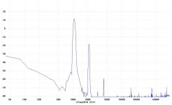
Here's a fft of my SE amp with this tube, and ok, the second is high, but way below audible, and everyone who's heard it loves the sound. It uses zero NFB.
I'll admit it, the 2A3 is better, but for the price the 6AS7 is great.
The 6AS7 gets a lot of unfair discredit. It is a very linear tube, but it does require a very large drive signal.
Another thing is with the low rp and usually relatively high currents the power supply will normally have high ripple that shows at the output.
Both the above can be easily fixed.
True, the two triode sections are poorly matched, but I've never had a big problem with that.
I've used these tubes for years, and they never fail.
The tube makes musical amps and has great bass in all amps I've used it with.
Here's a fft of my SE amp with this tube, and ok, the second is high, but way below audible, and everyone who's heard it loves the sound. It uses zero NFB.
I'll admit it, the 2A3 is better, but for the price the 6AS7 is great.
Attachments
Small amount?
Small amount slightly reducing 2'nd order distortions turns them into grass of high order ones. Feedback is like a gun: if you took it use it, or don't take at all instead of using "small amount".
Yeah, that amp needs at least 20dB of feedback.
The more I see the less I like, 6H8C and 6as7... you won't feel like making another tube amp after hearing this one.
Seriously, you need more gain. Change the driver tube.
My five cents: Build this amp with the parts you have now. You'll love it;
The 6AS7 gets a lot of unfair discredit. It is a very linear tube, but it does require a very large drive signal.
Another thing is with the low rp and usually relatively high currents the power supply will normally have high ripple that shows at the output.
Both the above can be easily fixed.
True, the two triode sections are poorly matched, but I've never had a big problem with that.
I've used these tubes for years, and they never fail.
The tube makes musical amps and has great bass in all amps I've used it with.
Here's a fft of my SE amp with this tube, and ok, the second is high, but way below audible, and everyone who's heard it loves the sound. It uses zero NFB.
I'll admit it, the 2A3 is better, but for the price the 6AS7 is great.
What output transformer are you using?
I remember that bass was good but the rest wasn't.
Member
Joined 2009
Paid Member
Perhaps I need to prototype this on a big piece of wood whilst standing on a rubber mat.
My friend has offered some additional flexibility to the design - suggesting I use one input tube per channel and one output tube per channel.
I have the option to use the dual 6H8C at the input by cascading the two triodes for more gain (i.e. I have 2 of these tubes available if needed). I also have the option to use a 6C2C per channel for the input with higher mu and this uses the same socket as the 6H8C. I also have access to a pair of 6C19P's, but requires a different socket.
With one tube per output I could parallel both halves of the 6AS7 for more power.
Too many options might not be conducive to getting this built though...
Member
Joined 2009
Paid Member
If you have that many I would just go for a push-pull design and drive it with a preamp, it would give you an excuse to build another project to learn tubes.
I'm beginning to realize this design could grow out of all proportion ! - especially as the more I read about tubes the more interesting they become and the more topologies I want to try. However, without a clear goal in mind this isn't going to stay on track. So I'm going to impose the limitation that it stay SE, single triode per input and the output will be the 6AS7 with option to try a triode-wired EL84.
I've been reading. I am starting to understand the concerns about the need to adequately drive the grid of this output tube with something that has more gain than the 6SN7 but I would still like to hear the design with the 6SN7, the question is which other tube should I plan to try on the input ?
I have found some other examples of amplifiers with a similar topology to Cellini which also use a SE 6AS7 output.
5687

===
One guy used a 5687 driver for his 6AS7, which has a mu of 18 and 'loved the sound'. But this has even less drive than the 6SN7 so I'd be no further ahead in getting more drive for the output tube. REJECTED
6SL7
===
There is a favourable review of a related design [http://www.6moons.com/audioreviews/fi6/421A.html] offering both 6SN7 and 6SL7 at the input. The reviewer preferred the latter. Trouble is, the plate resistance of the 6SL7 is a whopping 44k. My 155c choke simply doesn't offer enough load impedance to avoid killing the frequency response of my amplifier with this tube at the input. I want to keep the 155c choke load. So I'm going to give up on the option of the 6SL7.
E88C/6DJ8/6922/6N1P

==============
Lilliput uses the E88C with a mu of 33. As far as I understand, this tube is similar to the 6DJ8 / 6922 tubes which also have mu in the range 28 - 33. With my choke load for the input tube I might be able to realize a bit more gain than the original Lilliput. The plate resistance of these tubes is not as low as the 6SN7 but still perfectly acceptable.
There appears to be a lot of good opinion on the 6N1P as a better choice over the 6DJ8 and 6922 because of 'sound' - whatever this means. It also offers a mu of around 33 which is 50% better than the 6SN7. However, plate resistance is considerably higher, but I figure at 4.4k it's still OK with 155c choke (although gain is down by 0.7 at 20Hz). It's got a greedy heater though.
Last edited:
Member
Joined 2009
Paid Member
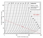
I've attached the curves for the 6AS7 from the Svetlana datasheet and I've drawn on what I think is the 2k5 loadline for the primary of the 125ESE output transformer.
I've positioned the loadline to intersect with the operating point that I often see used in published designs for this tube - B+ around 210V, Ip around 60mA (which is half the max rating).
Looking at the plate voltage with respect to the cathode means with Vgrid at -60V I use 150V plate voltage on the curves
Plate dissipation is therefore around 150 x 0.06 = 9W, within the max rating.
Have I got this right ??
Attachments
Last edited:
Edit: forgot to take into account the -60V cathode bias
Load line looks fine.
You know, it's a little awkward to make an amp which could take both 6as7 and el84, since the B+ is very low for the el84. Unfortunately there are not a lot of tubes to play around with in this voltage range. 6c33c maybe...
Kenneth
Load line looks fine.
You know, it's a little awkward to make an amp which could take both 6as7 and el84, since the B+ is very low for the el84. Unfortunately there are not a lot of tubes to play around with in this voltage range. 6c33c maybe...
Kenneth
Last edited:
You know, it's a little awkward to make an amp which could take both 6as7 and el84, since the B+ is very low for the el84. Unfortunately there are not a lot of tubes to play around with in this voltage range. 6c33c maybe...
12L6GT or 50L6GT
Member
Joined 2009
Paid Member
Edit: forgot to take into account the -60V cathode bias
Load line looks fine.
Yes, it was a bit of a revelation in the small hours of the night
Power vs Distortion on 6AS7
==================
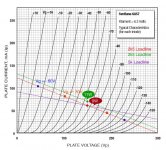
So if I understand what I'm doing here, I have biassed the output to 9W plate dissipation, about 70% of maximum rating which seems a safe place to be.
Looking at the curves the 60mA plate current means higher distortion for a +/- 60V swing on the grid. See plot. Looks like the current swings + 42mA /- 33mA about the operating point (blue dots) and based on some calculations I've seen somewhere on the internet this is roughly 6% THD [1]. At a +/- 30V swing on the grid (orange squares) this drops to around 2.5%.
Increasing biass to operate at 11W (85% max) gives me 70mA plate current and lower distortion. With the same +/- 60V on the grid it looks like the current swings +41mA / -35mA about the operating point and this is roughly 3.9% THD. This tube wants to run hot.
[1] THD = 100% x ((Ipmax + Ipmin)/2 - Ip0)/(Ipmax-Ipmin)
Input Gain
=======
For max output based on +/- 60V of swing on the grid (matching the data sheet which suggests 250V p-p between the grids of a PP pair which is +/- 62.5V for SE) I'd need an input stage gain of 42 or 21 for a source that puts out 1Vrms or 2V rms respectively.
In addition the tubes I mentioned above, there's another input tube I'm wondering about is the 6C45/6C4PI as it offers mu of 50 with low plate resistance. I gather that it needs precautions against oscillations (grid stoppers and heater ferrites). Anybody have more information on this tube ? will it be happy at 8mA ?
12L6GT or 50L6GT
Is that a 50V heater ? - wow. My trafo doesn't give me a convenient option for generating 12V or 50V heater power.
I am interested in the 6A3 though, I am wondering if it would give me the means to try out a DHT in the Cellini as a swap for the 6AS7.
Attachments
Last edited:
is that a 50v heater ? - wow. My trafo doesn't give me a convenient option for generating 12v or 50v heater power.
6aq5
An externally hosted image should be here but it was not working when we last tested it.
Hi Bigun,
I'm not 100% sure, but I thought that formula [1] was only for the second harmonic, not THD? I should check for myself...
Another option to get a higher input sensitivity would be, to use a small input transformer before the 6sn7. You could try to scrounge one off an old microphone amp or so.
Kenneth
Member
Joined 2009
Paid Member
I happen to have a pair of Hammond 835 interstage transformers in my junk box. They have a limitation that they can't suffer any dc biass current. These transformers have two primaries and two secondaries so perhaps they can be wired to achieve a 1:2 voltage step-up. Another limitation is their limited frequency response, they are the less expensive broadcast version with rolls off from 15kHz.
I'm not sure as to their suitability ?
p.s. Yes, you are right, the formula is good for H2 only but I figure that H2 is so dominant that the error margin of my caculations are much larger than the distortion contributions from higher harmonics. I guess I could also run a simulation.
I'm not sure as to their suitability ?
p.s. Yes, you are right, the formula is good for H2 only but I figure that H2 is so dominant that the error margin of my caculations are much larger than the distortion contributions from higher harmonics. I guess I could also run a simulation.
- Status
- This old topic is closed. If you want to reopen this topic, contact a moderator using the "Report Post" button.
- Home
- Amplifiers
- Tubes / Valves
- my CELLINI triode amp