Hi,
3. When matching tubes, what criteria should one use, matching on a certain input giving a certain output or a certain change in input giving the same rate of change (steepness?) in the output of the two tubes? Or both perhaps? I understand that matching is not an issue with the M-60 but I had to grab this opportunity as there are so many people here that would know the correct answer.
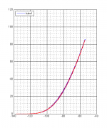
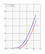
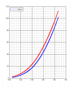
I'm wondering just the same thing. I've begun to measure the curves of some 6H13C and I'm not sure how to match. Similar slopes makes sense to me, though I can see how this will compromise distortion levels as the power is ramped up. I attach a few tube curves where I compare the two triodes. x-axis is grid voltage, y-axis is cathode current, the cathode resistor is 100 ohms, so some degeneration is going on. Plate voltage about 160 V.
Attachments
Good, so the question has some general interest maybe.
I agree the slope is probably the most important parameter. If the steepness is the same then maybe if they start rising a bit apart, is perhaps not that important. This statement is probably dependent on in which circuitry these two tubes are being used.
Nice curves!
I agree the slope is probably the most important parameter. If the steepness is the same then maybe if they start rising a bit apart, is perhaps not that important. This statement is probably dependent on in which circuitry these two tubes are being used.
Nice curves!
Alternate Transformers...........
I have many of the old TEK scope transformers from 531/541 scopes laying around the shop and was hoping I would be able to build the M-60 with these or at least cover most of my bases with them. What are your thoughts?
I have many of the old TEK scope transformers from 531/541 scopes laying around the shop and was hoping I would be able to build the M-60 with these or at least cover most of my bases with them. What are your thoughts?
Attachments
Start reading post 144 and down to see what you need a power supply.
http://www.diyaudio.com/forums/tubes-valves/161112-what-tubes-tube-amp-15.html
Post #109 has Atmasphere schematic of the P/S.
http://www.diyaudio.com/forums/tubes-valves/161112-what-tubes-tube-amp-15.html
Post #109 has Atmasphere schematic of the P/S.
I'm wondering just the same thing. I've begun to measure the curves of some 6H13C and I'm not sure how to match. Similar slopes makes sense to me, though I can see how this will compromise distortion levels as the power is ramped up. I attach a few tube curves where I compare the two triodes. x-axis is grid voltage, y-axis is cathode current, the cathode resistor is 100 ohms, so some degeneration is going on. Plate voltage about 160 V.
As the tubes age, our experience is that they tend to be much more matched in time as opposed to brand new. Of course that experience is based on using a Hickok transconductance tester that is far less comprehensive.
FWIW none of the review samples ever sent out has used matched tubes...
Some people have installed test jacks wired to the cathode resistors so they can use the amplifier itself as a tube tester. This allows one to test a lot more tubes at a time
")
I'm planning to build M60, so I have a few questions:
- in the bias circuit of schematics posted from atmasphere there are 2 resistors (49.9Kx2 for 235v) that could replace 22.1K and 110K. What does it means?
- what is the wattage dissipation of resistors when non specified?
- in power supply, what do you think about to add a film capacitor close to each power tube (in place of single capacitor 100 uF C21-C22), to provide limited but instantaneous current when needed from output stage?
Hi Andrea !
With 2 x 49,9K instead of 22,1K&110k mean that bias resistors network is than arranged for 235VAC main voltage , which is usual net voltage for most European country .
My personal opinion that is not necessary to ad any small film capacitor close to each power tube instead of two 100uF bypass block caps .
Two 100k on anodes of V2 have to be around 1W rated , with 1% tolerance or less , high quality resistors .
By CCS V3 tube 34,7K kathode resistor shold be around 2w rated , 1% tolerance , high quality to .
Remain Amp resistors should be in range from 1/4 to 1/2W , 1% tolerance or less , high quality .
Best Regards !
Hi Banat,Hi Andrea !
With 2 x 49,9K instead of 22,1K&110k mean that bias resistors network is than arranged for 235VAC main voltage , which is usual net voltage for most European country .
My personal opinion that is not necessary to ad any small film capacitor close to each power tube instead of two 100uF bypass block caps .
Two 100k on anodes of V2 have to be around 1W rated , with 1% tolerance or less , high quality resistors .
By CCS V3 tube 34,7K kathode resistor shold be around 2w rated , 1% tolerance , high quality to .
Remain Amp resistors should be in range from 1/4 to 1/2W , 1% tolerance or less , high quality .
Best Regards !
thanks for reply.
I'm in Italy, so I have to use 2 x 49K9 resistors.
About small capacitors close to each power tube, a few years ago I built an amplifier using parallel of mosfet device in the output stage. During one of the several listening session I placed one WIMA MKP4 10uF capacitor close to each mosfet and amplifier became more responsive to transient. Piano attack in the first movement of Beethoven piano sonata Patetica became more realistic. So I was thinking to add small capacitors as above.
About cathodes and anodes resistors, I'm thinking to decrease values to 18K2 and 50K as in schematics V1.0 posted from mullardel34, increasing driver stage bias current from 2.5 to 5 mA. So I believe I have to use both 2W rated resistors. Is it right?
About resistors quality, I'm planning to use Shinkoh tantalum resistor in the signal path, Caddock and Vishay for driver anodes and cathodes resistors, and Kiwame as cathode resistors in the output stage.
One more question: what do you think about using DC to heat all filaments?
Andrea
Andrea
Don`t know why happened that sonic improvement when you have bypassed each power Mos Fet in that SS Amp ! , maybe you than have stopped oscillation somewhere in MHZ range , since the power Mos Fet tend to oscillate there easy if DC power line is to long , heatsink non earthed correct , or electronic components layout is not done properly, .......
Atma-Sphere M60 tube power Amp don`t have that sort of problems ,
simply M60 it is very good electronicaly designed Amp , which usually work unconditionally stable , even with worse DIY electronic components layout .
It is enough to follow the original Atma-Sphere M60 electronic components layout , or to design similar DIY chassis which follow original Atmasphere layout solutions .
You don`t have to increase resistors power rate if you decrease that resistors value .
BTW that`s resistors is integral parts of input voltage Gain stage ( V1,V2,V3 ) but not the parts of driver stage ( V4 ) ! .
DC filaments supply it is not necessary for this power Amp , with that DC filaments supply you well unnecessary spend more money and unnecessary well complicate your Amps .
Shinkoh , Caddock ,Vishay and Kiwame - not bad choice !
Personally I use Russian standard MIL resistors ( when available ), or second hand resistors from old PC CRT Monitors founded on closest junk yard , with 100% of electrical & sonical success !
I'm planning to build 2 separate blocks for each channel (12 output tubes per channel instead of 8 as in the originale schematics), one for signal and one for power supply, so I have about 30-40 cm of DC power line from supply to output stage, and then I consider to add polypropilene capacitors close to each tube, to provide an energy tank, limited but very fast, and improve transient response.
Ops.. I wrote driver stage, but I would write input stage (V1, V2, V3). Assuming 5 mA bias current and 50K anodes resistor and 18K2 cathode resistor:
- 50K: 5 mA * 50K = 250V then 250V * 5 mA = 1,25 W
- 18K2: 5 mA * 18K2 = 91V then 91V * 5 mA = 0,455 W
Is that Right?
Andrea
Ops.. I wrote driver stage, but I would write input stage (V1, V2, V3). Assuming 5 mA bias current and 50K anodes resistor and 18K2 cathode resistor:
- 50K: 5 mA * 50K = 250V then 250V * 5 mA = 1,25 W
- 18K2: 5 mA * 18K2 = 91V then 91V * 5 mA = 0,455 W
Is that Right?
Andrea
Andrea
If I understand you correct you want to build Separate PSU chassis ( box) from Amplifier Chassis , if so than personally I think that is generally Bad idea !!! ,
since power loss in interconect cable well be to high , special introduced losses in filament conductors for 12 power tube ( 12x2,5A=30A ) !!! .
You can expect to many negative interactions between multicore PSU cable conductors to , since than in that 30 -40 cm long cable you well have wrapped together many different PSU conductors ,.......
Maybe Mr. Ralph Karsten have right answer here and solution , since he all ready designed and produced most powerfull OTL Amp -MA3- ,which I think have Separate PSU chassis(box) from Amp Unit chassis.
About that resistors power rate value:
Input Voltage gain stage is not supplied from single +250 V rail but from bipolar B+ & B- rail ( + - 300V ) , to efficiently drive 12 power tube instead of 8 you have to slightly rise that bipolar supply voltage up to +- 350V , so than you have to rise the power rate for that three resistors to .
Anyway than 2W for both V2 anode resistors well be OK value , and 3 W for V3 CCS cathode resistor is OK to .
banat
it's very difficult to find a commercial enclosure to fit all parts (transformers, capacitors, tubes, ..), so I'm thinking to build 2 separate blocks. BTW I'm planning to join mechanically the blocks, to avoid cable and connectors, simply I pass several wires from PSU block to amp block.
atmasphere
thanks for tips.
what do you think about heat power tube filaments in series instead of in parallels, to decrease drastically current required?
Also, do you think that -325V/+325V for the input stage and +310V/-310V for the driver stage are sufficient to drive 12 output tubes?
Thanks all
Andrea
Buenos dias
Hi to everybody, on the past at least twice I asked to this blog , I don't know if my language is not eloquent nor intelligible, I speak better Spanish cause I come from Argentina with the worst combination because at least I live on Spain.
Sorry to this community for interrupt, but nobody answer my previous interruptions. Now I ask a different theme, course related to this OTL. Now with the honour of been listen for many popes of the big audio community specially now I recognize (sorry for omit the others) The AtmaSphere's Ralph, receive my respects and a couple of questions:
One: Several years ago I got a OTL with 20 AS7GA with driver "A la Makovsy" same like Bruce Rosemblitz article in GAudio magazine (I collect all the issues in Argentina and miss them) without the first valve amplifier. Its name is Craig Mertz and come with two Avel Lindberg monster trannies for the amp, a couple of stupid power supplies for the preamp and for the heaters all the power valves in serie connection for the 120VAC you have there on the States. The amp blewup all the fuses and come with extra bag of many of them, and a soon rechanged with each peaks did the same and the bag was empty. I Stopped and plain first change some parts but with the time I decide to change to a Circlotron topology. At first time I make many tribulations because I have many amps. but finally I decide to change 'a la Atmasphere' form. The first question to Ralph is:
A)Without the upper double triode in the differential cascode how much gain lost?
For the heaters I find SMTP from 5 to 8 volts regulated 350watt ones for 30 euros.
B) is possible to use switching power supply?
The transformations of the power supply get a little extra voltage for the bridges: 125 x √2 = 176vcc.
C)Is possible to use a Solid State voltage regulator for each bridge supply?
Muchos saludos para todos. Many regards for all.
atmasphere
thanks for tips.
what do you think about heat power tube filaments in series instead of in parallels, to decrease drastically current required?
Also, do you think that -325V/+325V for the input stage and +310V/-310V for the driver stage are sufficient to drive 12 output tubes?
Thanks all
Andrea
You should be able to make that work in both cases.
A)Without the upper double triode in the differential cascode how much gain lost?
For the heaters I find SMTP from 5 to 8 volts regulated 350watt ones for 30 euros.
B) is possible to use switching power supply?
The transformations of the power supply get a little extra voltage for the bridges: 125 x √2 = 176vcc.
C)Is possible to use a Solid State voltage regulator for each bridge supply?
Muchos saludos para todos. Many regards for all.
Without the top tube in the cascode the gain is reduced about 12db.
You can use a switching power supply; keep in mind that the amplifier has a lot of bandwidth so noise could be an issue, but with modern switching supplies this should not be a problem.
176V is rather high so there would be no illusions of class A, but you could make that work. Now OTOH if you regulated the voltages down a little, that could be quite interesting. However keep in mind that if a 6AS7G arcs, the regulators would be at risk so you will want to take precautions in that regard!
Thanks Sir.
Thanks for share your knowledge.
The another option is putting the primaries on series and reduce the total voltage until 176/2=88volts. There are a article in GA from the issue 4/92 if I remember the exactly name of Clive Locke. I remember you Ralph did refute through a warning in the number following of GA and for which I received from Atmasphere the document that noticed that it was a copy of a model that never left on sale and for which you recommended 12AT7 instead of 6DJ8, in this article the voltage of the power supply was of 90 volts.
I just read the John Harper mods for MA60 kit, Do you still sustain that 6BX7 on step of the catode follower 6SN7, 6BL7 is better?
Thanks again.
Without the top tube in the cascode the gain is reduced about 12db.
You can use a switching power supply; keep in mind that the amplifier has a lot of bandwidth so noise could be an issue, but with modern switching supplies this should not be a problem.
176V is rather high so there would be no illusions of class A, but you could make that work. Now OTOH if you regulated the voltages down a little, that could be quite interesting. However keep in mind that if a 6AS7G arcs, the regulators would be at risk so you will want to take precautions in that regard!
Thanks for share your knowledge.
The another option is putting the primaries on series and reduce the total voltage until 176/2=88volts. There are a article in GA from the issue 4/92 if I remember the exactly name of Clive Locke. I remember you Ralph did refute through a warning in the number following of GA and for which I received from Atmasphere the document that noticed that it was a copy of a model that never left on sale and for which you recommended 12AT7 instead of 6DJ8, in this article the voltage of the power supply was of 90 volts.
I just read the John Harper mods for MA60 kit, Do you still sustain that 6BX7 on step of the catode follower 6SN7, 6BL7 is better?
Thanks again.
- Home
- Amplifiers
- Tubes / Valves
- What tubes for a OTL tube amp?