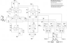
Curiosity, can someone explain what the resistor and cap are for across the output terminals in the schematic.
I assume a filter of some sort?
I get the 600ohm resistors as a reference to ground.
Just has me wondering as I am no electronics engineer.....
Really appreciate the insight!
I assume a filter of some sort?
I get the 600ohm resistors as a reference to ground.
Just has me wondering as I am no electronics engineer.....
Really appreciate the insight!
Attachments
Curiosity, can someone explain what the resistor and cap are for across the output terminals in the schematic.
I assume a filter of some sort?
I get the 600ohm resistors as a reference to ground.
Just has me wondering as I am no electronics engineer.....
Really appreciate the insight!
The resistor and cap , are there to keep the output impedance of the amp near 8ohm at high frequencies , they have an Fc of about 212KHz .
Thank for the extra clarity Dimitris!
PET240, are you planning a set of these amps? Or are you in the process?
I'll help if I can.
Heya,
Yes I have most parts now, transformers are being wound now, they joys of Oz, cheaper to get made than off the shelf once shipping comes into it.
Am allowing enough B+/heater current to allow the 6336 tube to be used as well if I like their sound.
Have sorted all the other stuff as well, then it will just be the build time....
Was curious regards your SMPS mod.
Any hints as to build process to use?
Thanks,
Drew.
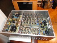
sounds cool....or hot") Not sure about the filament requirements of the 6C33C but it couldn't be too far off 10 6N13S'. I just wired the heaters series parallel to get the required 6.3V per tube. They were surprisingly equal when measured varying around .1V or .2V. The SMPS has a fine adj. to tweak the voltage. Chassis is deep enough to attach the PS to the inner side of the bottom cover. I ran the power through a common mode filter to clean it up. I think one advantage of this I think is that the heaters all go out at once is if there's an issue. Prevents leaving one bank of power tubes remaining lit with the other out.
Not sure about the filament requirements of the 6C33C but it couldn't be too far off 10 6N13S'. I just wired the heaters series parallel to get the required 6.3V per tube. They were surprisingly equal when measured varying around .1V or .2V. The SMPS has a fine adj. to tweak the voltage. Chassis is deep enough to attach the PS to the inner side of the bottom cover. I ran the power through a common mode filter to clean it up. I think one advantage of this I think is that the heaters all go out at once is if there's an issue. Prevents leaving one bank of power tubes remaining lit with the other out.
I'm an amateur radio guy so I have a prodigious junk box and used a good bit of on hand stuff to build these.
Not sure about the filament requirements of the 6C33C but it couldn't be too far off 10 6N13S'. I just wired the heaters series parallel to get the required 6.3V per tube. They were surprisingly equal when measured varying around .1V or .2V. The SMPS has a fine adj. to tweak the voltage. Chassis is deep enough to attach the PS to the inner side of the bottom cover. I ran the power through a common mode filter to clean it up. I think one advantage of this I think is that the heaters all go out at once is if there's an issue. Prevents leaving one bank of power tubes remaining lit with the other out.I'm an amateur radio guy so I have a prodigious junk box and used a good bit of on hand stuff to build these.
Nice !!! , i have built two OTL amps with PL36 , one Futterman output topology and the other Circlotron and they realy sounds very good ! .Finally completed my M-60's. Sound is incredible.
PET240 count me too if you need any help ! .
Last edited:
Well , The Futterman sounds better to my ears , but this is due to better design in input and driver stages and not due to the output stage itself .Photos.....please? How does the Futterman sound compared to the Circlotron?
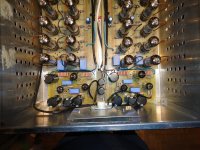
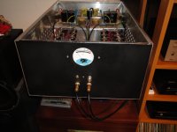
Some photos of the Futterman OTL ( FELINE OTL AMP )
Attachments
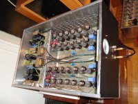
Super Nice! The circuit boards are a nice touch. What are you driving your amps with? I'm currently using a 6SN7 Aikido that I built a couple years ago. Thinking about breaking out my Salas 6V6 line pre-amp and redoing it to a little better standards than the original build I did several years ago.
Thanks , but your amp looks more " sexy " .
I have three different preamplifiers , designed and built with the same way of design but with different tubes.
The first stage is always a differential amp the second is a common cathode amp and the third is a cathode follower , with the use of local and global negative feedback !.
. I have three different preamplifiers , designed and built with the same way of design but with different tubes.
The first stage is always a differential amp the second is a common cathode amp and the third is a cathode follower , with the use of local and global negative feedback !.
You made a beautiful amp man!Some photos of the Futterman OTL ( FELINE OTL AMP )
I can't help but to wonder how much power you could get out of 12 tubes per channel with an OPT though... If they were KT88 you'd have over 400W!
- Home
- Amplifiers
- Tubes / Valves
- What tubes for a OTL tube amp?