Is this just for two 26 tubes? If so where does the 30mA come from? 26 is a max of 7mA each.
Hi Andy!
Ahhh yes, my mistake(roughly 6.2 mA each). Other than that, it's okay? I am shooting to use the supply for 01A as well.
Hi everyone,
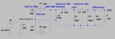
I am building a new PSU for my 26. Please comment on the schematic and chart below for HT. Thanks!
Abe
hello Abe,
A small cap to ground (at rectifier → L1 node): 680nF 1000V MKP is useful to control that node a little better; and another the same (or just 220nF 400V/630V) after the final low-value choke. The effect of the small-value choke is optimised if the loop around the final two caps + the 320mH choke is physically small (short wiring).
Other than that, you are all set!
Thank you Rod! I will add the caps to the circuit.
Abe
Hi everyone,
I am building a new PSU for my 26. Please comment on the schematic and chart below for HT. Thanks!
Abe

Hi Abe,
Take what I say with a huge mound of salt, as I am one of those accursed perpetual beginners. I have no EE background.
BUT! I do have some experience that directly relates, regarding the type 26 and HT power supplies:
(If you are going to use a regulator after the PS filter section you modeled in PSUD2, then you can likely disregard what I am about to suggest.)
Looking at the filter Q of your LC sections, you are making very narrow bandwidth filters. Your first filter has a Q of roughly 5.8, and your second filter has a Q of roughly 2.1. A good rough guideline (I have read, and this has worked in practice) is to shoot for something close to a .707 to .5 range of Q factor. These are much wider-band Qs than what you have.
In PSUD2, these filters may model well, not showing any ringing or overshoot on the graph, but in reality are a bit less ideal than they look.
The reason I bring this up is that I tried to power my 26 with a passively filtered PSU with narrow Qs, and the ringing of the filters caused motor-boating in the preamp. When I increased the capacitance or resistance to hit the .707 target, the motor-boating went away.
My signal cicuit is a VERY simple one and PSRR is poor. If you are using a CCS or MU follower or gyrator, you may not have the same problem.
Try it the way you have planned for sure, but maybe have some 10W wire-wound resistors on hand to add in series with your chokes to tune the Q if necessary.
I'm thinking roughly 600R extra for your first filter, and 300R for the second.
Just something to keep in mind if you end up with troubles. (not saying you will)
Regards,
John
Thank you for the suggestion! Yes, I will have Salas Shunt Regulator after the PS filters.Hi Abe,
Take what I say with a huge mound of salt, as I am one of those accursed perpetual beginners. I have no EE background.
BUT! I do have some experience that directly relates, regarding the type 26 and HT power supplies:
(If you are going to use a regulator after the PS filter section you modeled in PSUD2, then you can likely disregard what I am about to suggest.)
Looking at the filter Q of your LC sections, you are making very narrow bandwidth filters. Your first filter has a Q of roughly 5.8, and your second filter has a Q of roughly 2.1. A good rough guideline (I have read, and this has worked in practice) is to shoot for something close to a .707 to .5 range of Q factor. These are much wider-band Qs than what you have.
In PSUD2, these filters may model well, not showing any ringing or overshoot on the graph, but in reality are a bit less ideal than they look.
The reason I bring this up is that I tried to power my 26 with a passively filtered PSU with narrow Qs, and the ringing of the filters caused motor-boating in the preamp. When I increased the capacitance or resistance to hit the .707 target, the motor-boating went away.
My signal cicuit is a VERY simple one and PSRR is poor. If you are using a CCS or MU follower or gyrator, you may not have the same problem.
Try it the way you have planned for sure, but maybe have some 10W wire-wound resistors on hand to add in series with your chokes to tune the Q if necessary.
I'm thinking roughly 600R extra for your first filter, and 300R for the second.
Just something to keep in mind if you end up with troubles. (not saying you will)
Regards,
John
Abe
I will have Salas Shunt Regulator after the PS filters
You will most likely have no problems, then.
However, if you did get a couple resistors, you could try it with and without the shunt reg. The two options sound just a little bit different.
Of course, you would need dropping resistors, too. But, it’s not much of an investment parts-wise. Those Yaego wirewounds are less than a buck a piece. Also 10W is overkill but they will stay nice and cool.
Also, don’t forget the bleeder resistor, or you won’t get the voltage you are expecting.
I’m sure you know that already. I just mention it because you modeled for a 30mA draw. At 6mA the voltage will be much higher.
One can roughly simulate the bleeder in PSUD by inserting a current sink after the first LC stage. This will also give you a good (lazy/low math) guideline for how big to size the bleeder.
However it ends up, enjoy the new build!
Regards,
John
You will most likely have no problems, then.
One can roughly simulate the bleeder in PSUD by inserting a current sink after the first LC stage. This will also give you a good (lazy/low math) guideline for how big to size the bleeder.
However it ends up, enjoy the new build!
Regards,
John
Thank you John!
The effect of the small-value choke is optimised if the loop around the final two caps + the 320mH choke is physically small (short wiring).
Hi,
Open question if I can, what is the effect of the small-value choke as referenced above?.
Thank you.
HK
Hi,Is necessary the last LC?
This is my 01a HT raw PSU.
I am not the right person to answer but I have it as I am just following the other PSU builds using LCLCLC topology.
From my reading of the thread, I've seen CLCLC also (1uF C1, L1, 47uF for C2 and C3) then shunt regulator.
Abe
Is necessary the last LC?
It's not necessary - but it is a good precaution.
(small) L -- C (stacked film) should be effective at higher frequencies; and even if HF does not matter to the DHT preamp itself, supply filtering can help keep some of the HF (low MHz) away from a connected DAC.
HF on mains-power is increasing, due to the range of modern equipment connected, and running all the time.
DACs certainly need protection from HF, IME.
They are not very desirable. They are optimised only for helping equipment with mains→DC converters get through the statutory EMC regulations (EN5022, CISPR22 for IT gear, for example).
Line-to-Neutral capacitance is OK in moderate size (470nF class X2) but the class Y caps (Line to Earth, Neutral to Earth/Ground) and are best to be removed, or they will couple noise into the safety-earth, that might otherwise be blocked by your power transformer.
The series inductance (differential mode) is unhelpful where you have pulsed current (like DC supplies with cap-input filters).
I would prefer to keep a stock of Panasonic or EPCOS class X2 caps, around 470nF 275V AC, and apply those across the PT primary. What the PT does not block can be dealt with in the DC filter, as shown above.
In case of depletion FET cascode, the drain should already have a supply capacitor (stacked film for prefence, plus 47 to 100uF elko) to be certain of stability. This will usually take the place of the final caps in the LCLC too - unless the wires are very long.
So yes, the filtering will suffice, like this, when you have an SSHV.
So yes, the filtering will suffice, like this, when you have an SSHV.
Hi All,
Just a quick note. I built up Ale's Hybrid Mu Followers and tried them with the 26. Contrary to a couple of posts I read a while back in this thread, I think think they play very nicely with the 26!
Extremely clean, but not sterile at all. Lots of texture and very even frequency response.
I am using them at a lower operating point, around 4.5mA. For some reason, as I fiddle around with the 26, I keep dialing down the current.
I know this is an old product for you already, Ale, but Bravo! (and thanks for sharing!)
Regards,
John
Half on-topic, half off-topic
So, I have very much been enjoying the 26 with the Gyrator boards and filament bias.
As it stands, though, my system has too much overall gain which leads to a bit of unnecessary noise.
The main fault is that I am currently using Mullard 5-20 style amps, but I have the NFB loop disconnected, because I like it a little better this way. However, this means that the amps have and extra 20 db of gain.
What I am wondering is, with the Hybrid Mu Followers, will the 26 have sufficient drive to allow me to skip the voltage amp stage of the amplifiers and go straight to the grid of the ECC83 phase splitter? (keeping the grid stopper in place)
Or would this be better done with a different tube? (4P1L, etc)
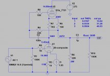
My amps are based on Claus Byrith's schematic from the Lundahl website. The voltage amp is still an EF86, but triode-strapped to give a Mu a bit less than 25 given the operating conditions. (schematic attached for convenience)
I tried it a while back when when the preamp was RC coupled and it didn't work at all. It was noisy and distorted. But with RC coupling the Rp of the 26 was quite high.
Thanks in advance for your input!
Regards,
John

So, I have very much been enjoying the 26 with the Gyrator boards and filament bias.
As it stands, though, my system has too much overall gain which leads to a bit of unnecessary noise.
The main fault is that I am currently using Mullard 5-20 style amps, but I have the NFB loop disconnected, because I like it a little better this way. However, this means that the amps have and extra 20 db of gain.
What I am wondering is, with the Hybrid Mu Followers, will the 26 have sufficient drive to allow me to skip the voltage amp stage of the amplifiers and go straight to the grid of the ECC83 phase splitter? (keeping the grid stopper in place)
Or would this be better done with a different tube? (4P1L, etc)
My amps are based on Claus Byrith's schematic from the Lundahl website. The voltage amp is still an EF86, but triode-strapped to give a Mu a bit less than 25 given the operating conditions. (schematic attached for convenience)
I tried it a while back when when the preamp was RC coupled and it didn't work at all. It was noisy and distorted. But with RC coupling the Rp of the 26 was quite high.
Thanks in advance for your input!
Regards,
John
I can only say build it and try it - yes, you should be able to take the EF86 out and directly drive the phase splitter. You can put 7mA through a 26.
I'm not sure how much gain you need, though. Have you considered using the EL34 outputs in triode?
In my 300b SE amp with 4P1L as driver I ended up short of gain and I used a simple chi-fi op-amp stage at the input, currently a LM4562. This works remarkably well to my surprise.
I'm not sure how much gain you need, though. Have you considered using the EL34 outputs in triode?
In my 300b SE amp with 4P1L as driver I ended up short of gain and I used a simple chi-fi op-amp stage at the input, currently a LM4562. This works remarkably well to my surprise.
What I am wondering is, with the Hybrid Mu Followers, will the 26 have sufficient drive to allow me to skip the voltage amp stage of the amplifiers and go straight to the grid of the ECC83 phase splitter? (keeping the grid stopper in place)
Like this?
Attachments
- Home
- Amplifiers
- Tubes / Valves
- #26 pre amp