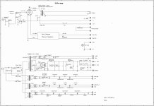
Like it says - HT to 18 , anode to 13, join 16 to 21
2+3+9+10 to grid
4+5+7+8 to ground
2+3+9+10 to grid????
2+3+9+10 to grid????
Grid of next stage. I'm sure you understand all this.
Hi
I have also built a prototype of 26 type tube based preamp. I have used UTC HA133 transformers as well as capacitor output (Vitamin Q 96p 1uf with 470k resistor from output to ground).
B+ is AZ1 mesh with LCLCLC (Tribute 20H + 47uf BG WKZ + Chicago 12H + 47 BG WKZ + Partridge 10H + 0.22 Copper foil pio)
Two filament transformers from AE Europe 15v 4A, 6800uf ELNA + 250mh 2A AE Europe + 6800uf Elna + 1ohm resistor + 47uf)
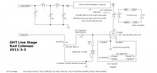
Rod Coleman Regs with filament bias using 10ohm Ohmite brown devil resistor.
As it is only a prototype that I will tune for the next several weeks - all is build on a square shaped wooden board with no shielding. There was some hum on my 105dB horns, so I've placed a 1mm brass foil between PSU and tubes/HA133 and connected it to ground which helped very much to minimise the hum. Right now it is very slightly audible only when the music is not playing.
At the very first stage I have listened this preamp with capacitor output with 470k load resistor on output. I didnt made a 1vs1 comparison to UTC HA133, but to be honest I didnt felt night and a day difference. Bass was definetely better with capacitor ouput.
I have tested several rectifiers like: Marconi 83, Fivre 5Z3, Fivre 5V4G, RCA 5Z3, RCA 5U4G ribbed plates, Philips 5u4G, Cunningham 80, Telefunken AZ1 globe mesh and Valvo AZ1 mesh.
5Z3 and 5U4G played a bigger sound, more lushed, IMO - oversized.
If I would not tried AZ1 - I would settled on Cunningham 80, however I found VALVO AZ1 globe mesh to be the most 3D and airy while keeping apropriate smoothness and musicality. Telefunken is IMO too analitical.
Right now I will test LCLCLC vs LCLCRC for B+. What are the rules when choosing last Choke/resistor and Capacitor in the chain?
I tried to simulate in Duncan PSU and found that 300ohm of the resistance with at least 0,47uf is the minimum to get the best results. With 4ohm of resistance and 0.1uf I found that the current looks terrible, at least in theory.
Same question with filament PSU - what value would you suggest for last resistor and capacitor in the CLCRC chain? At the beginning I had 0.1R with 10uf cap, but once more the current flow looks bad in Duncan PSU comparing to 1R with 47uf.
all the best
I have also built a prototype of 26 type tube based preamp. I have used UTC HA133 transformers as well as capacitor output (Vitamin Q 96p 1uf with 470k resistor from output to ground).
B+ is AZ1 mesh with LCLCLC (Tribute 20H + 47uf BG WKZ + Chicago 12H + 47 BG WKZ + Partridge 10H + 0.22 Copper foil pio)
Two filament transformers from AE Europe 15v 4A, 6800uf ELNA + 250mh 2A AE Europe + 6800uf Elna + 1ohm resistor + 47uf)
Rod Coleman Regs with filament bias using 10ohm Ohmite brown devil resistor.
As it is only a prototype that I will tune for the next several weeks - all is build on a square shaped wooden board with no shielding. There was some hum on my 105dB horns, so I've placed a 1mm brass foil between PSU and tubes/HA133 and connected it to ground which helped very much to minimise the hum. Right now it is very slightly audible only when the music is not playing.
At the very first stage I have listened this preamp with capacitor output with 470k load resistor on output. I didnt made a 1vs1 comparison to UTC HA133, but to be honest I didnt felt night and a day difference. Bass was definetely better with capacitor ouput.
I have tested several rectifiers like: Marconi 83, Fivre 5Z3, Fivre 5V4G, RCA 5Z3, RCA 5U4G ribbed plates, Philips 5u4G, Cunningham 80, Telefunken AZ1 globe mesh and Valvo AZ1 mesh.
5Z3 and 5U4G played a bigger sound, more lushed, IMO - oversized.
If I would not tried AZ1 - I would settled on Cunningham 80, however I found VALVO AZ1 globe mesh to be the most 3D and airy while keeping apropriate smoothness and musicality. Telefunken is IMO too analitical.
Right now I will test LCLCLC vs LCLCRC for B+. What are the rules when choosing last Choke/resistor and Capacitor in the chain?
I tried to simulate in Duncan PSU and found that 300ohm of the resistance with at least 0,47uf is the minimum to get the best results. With 4ohm of resistance and 0.1uf I found that the current looks terrible, at least in theory.
Same question with filament PSU - what value would you suggest for last resistor and capacitor in the CLCRC chain? At the beginning I had 0.1R with 10uf cap, but once more the current flow looks bad in Duncan PSU comparing to 1R with 47uf.
all the best
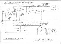
If you use -negative- battery potential on grid (and cathode grounded) MUST use input capacitor.
Not necessarily. I avoid an input cap by having an input transformer in the preamp, which isolates the DC from the preceding stage. I tried both cap and transformer and the LL1676 transformer sounded much better to me.
Why? Andy wrote all you need already - 4578 to ground, rca to ground too. I suggest you to read this article, it should help you plan proper grounding scheme of your system:
http://www.diyaudio.com/forums/diya...udio-component-grounding-interconnection.html
http://www.diyaudio.com/forums/diya...udio-component-grounding-interconnection.html
Why? Andy wrote all you need already - 4578 to ground, rca to ground too. I suggest you to read this article, it should help you plan proper grounding scheme of your system:
http://www.diyaudio.com/forums/diya...udio-component-grounding-interconnection.html
Thank you to clarify.
- Home
- Amplifiers
- Tubes / Valves
- #26 pre amp