Yup, it is on a dual rotary switch to display what tube is on the amp meter....
A couple of the amps that I've used this on, the 6JN6 variant was in process, new transformers and knobs to finish it up.
Hi Roline
Very cool..!
Tony:
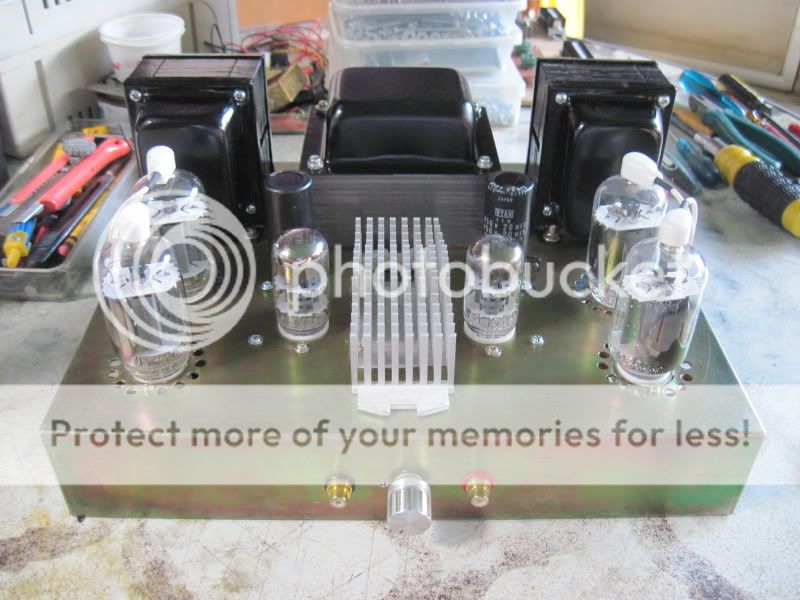
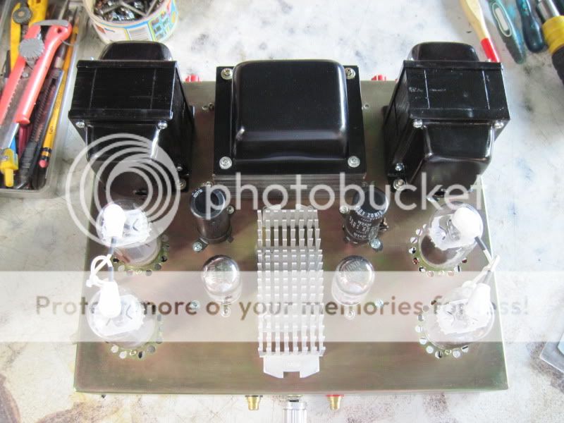
Very nice work. I am a fellow point-to-point DCPP guy. I like your big honkin transformers, too.
You did something that I did, which is to run the wires to the plate cap through the same hole, twisted. Don't repeat my mistake of hooking the caps up in reverse, as that creates positive feedback. I measured 740 volts AC on the primary of the output (I had wired up a power transformer for testing purposes). Probably lethal for output transformers, and the sizzle from the coupling caps was not encouraging.
My PL519 mono amps during an outdorr listening session at a friends house:
http://i496.photobucket.com/albums/rr327/Levande_2008/IMG_3416.jpg
http://i496.photobucket.com/albums/rr327/Levande_2008/IMG_3398.jpg
http://i496.photobucket.com/albums/rr327/Levande_2008/IMG_3389.jpg
http://i496.photobucket.com/albums/rr327/Levande_2008/IMG_3354-1.jpg
http://i496.photobucket.com/albums/rr327/Levande_2008/IMG_3416.jpg
http://i496.photobucket.com/albums/rr327/Levande_2008/IMG_3398.jpg
http://i496.photobucket.com/albums/rr327/Levande_2008/IMG_3389.jpg
http://i496.photobucket.com/albums/rr327/Levande_2008/IMG_3354-1.jpg
So here we go!!! Everything is ordered, apart from chassis mounted stuff. Received my first parts actually - IXYS current regulators (the hardest thing to come by out of US apparently - ordered few extra from DigiKey so I have some spare if anyone in UK or Europe is interested)
Mouser order is on the way too. I ordered everything from mouser as Mr. Millett provided in his BOM. It's my first project and I'm gonna go by the book and hopefully I'll learn some tricks as I progress with the project. Well that's the idea anyway. I'm a Live sound engineer and to understand the very fundamental laws and functions of the industry I decided to build an amp and came accross this project. Although I will try to add a volume control and several inputs as seen in several builds in here - so questions will follow
The mighty board should be sent out tomorrow as well as Mr. Millett is back from wherever he is so I hope I'll see it sometime within next couple of weeks and will be able to start filling the holes.
Meanwhile I just play the waiting game for now and keep reading all the posts as here's plenty of information about the build so thank you all for the contribution and sharing your knowledge and experience.
Hi Kabanos,
Just a shot from my amp to encourage you with your project:
[image]http://s11.postimage.org/5xerfd5qr/P2241046.jpg[/image]
Maybe 200 hours i'm using it now, and it ROCKS
Just a shot from my amp to encourage you with your project:
[image]http://s11.postimage.org/5xerfd5qr/P2241046.jpg[/image]
Maybe 200 hours i'm using it now, and it ROCKS
Fired up my DCPP yesterday (Completely stock configuration)
One channel making a grating static noise, found it to be a bad driver tube.
Listening to the 'good' tubes on the other channel and find it to be not all that good sounding. Not relaxed, congested, dark, boring.
This is not what it's supposed to sound like, so something must be wrong...
One channel making a grating static noise, found it to be a bad driver tube.
Listening to the 'good' tubes on the other channel and find it to be not all that good sounding. Not relaxed, congested, dark, boring.
This is not what it's supposed to sound like, so something must be wrong...
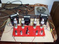
Sounds like my first impressions when I fired my Big Red Board up the first time. I was really disappointed but listened to it for a few days hoping something would break in, then decided to try a different winding on the outputs. I went from the 8 ohm winding to the 16 ohm series winding and the angels started to sing. My board is completely stock using Pete's recommended BOM. Power transformer is Hammond 369KX and outputs are 1650R. Tubes are an assortment of 6KD6. I purchased another 369KX to boost the board but am going to read the thread a few more times before I jump in. Anyone got an idea what I should expect for power with and without the second transformer?
Attachments
Anyone got an idea what I should expect for power with and without the second transformer?
How much raw (before the regulator) B+ do you have now?
Sounds like my first impressions when I fired my Big Red Board up the first time. I was really disappointed but listened to it for a few days hoping something would break in, then decided to try a different winding on the outputs. I went from the 8 ohm winding to the 16 ohm series winding and the angels started to sing.
That's good to know.
")
I have some more tubes on order (the bad driver tube was one of only four, so I don't even have enough to get the amp on and working properly...) Once the tube issue is resolved I will verify all voltages on the board, bias and balance it out, and let it burn in for a while. Then I will re-assess.
Raw B+ is 225 from the center tap and 446 across the red wires while in operation. The outputs are 10 pounds each and rated at 5000 using the 8 ohm winding and are rated for 100 watts. I also noticed that when I originally had the outputs wired I was not using both sets of windings as recommended and that may have been the reason for the crappy sound. Should I go back to the 8 ohm taps wired properly or leave it on the 16 ohm, or try both and go by ear? Speakers right now are an old cerwin vega satellite subwoofer system rated at 8 ohms. Currently the power transformer runs quite hot but I forgot to shut it off the other night and it was still about a five second interval before I had to pull my hand off of it so it seems to reach a peak and stay there. Anyways, thanks a million Pete for a fun well built project and also to George for all his input and help with making this board such a success.
Currently the power transformer runs quite hot
I looked up the Hammond 369KX and found it to be a bit on the small side for what you are doing. The 6.3 volt winding is rated for 6 amps. The 6KD6 draws 2.85 amps EACH, and you have 4 of them. Thats 11.4 amps plus 1.2 amps for the driver tubes. The little Hammond isn't going to put out over 12 amps for long.
I purchased another 369KX to boost the board
You need to connect up the second transformer immediately if only for the added filament power. The two 6.3 volt windings can be paralleled to increase the current capacity to 12 amps and avert a nuclear meltdown inside the single transformer. The phasing of the two windings must be correct to avoid sparks. This must be done by trial and error since the wires are both green.
To determine proper phasing wire the two primaries in parallel, tape up the HV secondaries, or use some means to avoid contact with them. Connect one green wire from each transformer together. Connect a DMM set on AC volts across the remaining green wires. Power up both transformers, and observe th DMM reading. It should be near zero, or near 12.6 volts. If you read 12.6 volts swap the green wires on ONE of the transformers, and repeat the test. Once you have a zero reading, those green wires can be safely connected together, and the green pairs can be used to provide 12 amps of heater power to the board. You can then tie the heater CT's together if you use them. Do not use the second HV winding until you are ready for the boosted B+ setup.
How much raw (before the regulator) B+ do you have now?
I was asking about the DC voltage after the rectifier diodes. This is measured across C6. With 225 volts of AC I would expect about 280 to 300 volts of DC. With this low voltage I would expect better results with the load on the 16 ohm tap. This reflects a 2500 ohm load to the tubes and that is probably about right for a 280 volt supply.
Once you set up the second HV winding for boosted B+ the tubes will see 550 to 600 volts of plate voltage. My guess is that you will get about 80 to 100 WPC with a 5000 ohm load, and 125 to 150 WPC (maybe more) if the tubes work well into a 2500 ohm load. I saw 250 WPC with 35LR6's (similar to the 'KD6) a 2500 ohm load and a 650 volt supply.
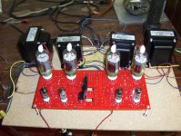
Thanks George, I have installed the second transformer as per your instructions and Chernobyl has been avoided. Bowie's Golden Years is now playing with no sparks or light show. I thought I had read the thread enough times and purchased transformers for 4 times 1.5 amps which is 6 amps. I appologize for the misunderstanding about the B+ as I was thinking before the rectifier instead of before the regulator. The voltage across C6 is 295 volts which is pretty much exactly as you said. I hopefully have all the upgrade parts for the "boost" which I will put together after reading the appropriate posts again and probably ask a few more questions to be sure I am following all the safety precautions. I am also considering using a Hammond 270 HX for the boost as it is too big for another project I have been working on. It is a 275-0-275 and the heater winding is also rated at 6 amps. This combination might put me close to your 250 watt setup, but I will need a crane to lift all of these transformers out of the basement. Anyways Ive included an updated picture as I know I like looking at projects in progress. ( :
Attachments
Can the 6CF6 be used as the driver tube interchangeably with the specified 6CB6?
Yes, but you may have a harder time getting them to balance for each channel. Worth a try IMHO.
NJ7P SQL Tube Database Query
jeff
A comparison of the data sheets shows they are very close to being the same tube. Close enough that you probably would see as much variations from manufacturer to manufacturer.
Gm 8K vs 7.8K, Plate Current 13mA vs 12.5mA, bias voltage at 20uA current -6.5V vs -6V, ...
I'd plug it in and tweak it.
Gm 8K vs 7.8K, Plate Current 13mA vs 12.5mA, bias voltage at 20uA current -6.5V vs -6V, ...
I'd plug it in and tweak it.
Can the 6CF6 be used as the driver tube interchangeably with the specified 6CB6?
I haven't tried that particular tube, but I ran about 30 different tubes through my red board in the driver sockets. I tried everything from triodes to heptodes. ALL of them worked! Some had lower gain than others, with the 6GU5 beam hexode being my favorite due to the extra gain. It is useful when driving big sweep tubes into the 100+ WPC region.
I have some questions regarding sweep tubes.
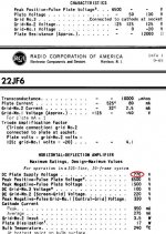
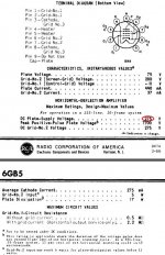
Please refer to the following snips from the data sheets from two different 17 watt sweep tubes. Both were designed for horizontal deflection TV service but reflect similar specs to many of the 17 and 18 watt cheaply available tubes.
However, I have circled major differences with regard to maximum plate voltage. Both have way high intermittent plate voltage and require plate caps but one has 275 volts max and the other 770 volts max steady state.
Is it possible the 275 volts max 6GB5 would be a better pic for the engineers amp as it runs on lower voltage and would not require the boost B+ to the push pull stage?
Asked another way, why the difference and could I run 600 VDC or so on the 6GB5 with no problem? I suspect I am missing something here.
Attachments
Watch for the # of pins, Compatron sweep tubes can be found in both 9 and 12 pin versions,
Don't forget 6JT6 and 17JT6 similar to the 6JN6 but 9 pinners.....
The big red board was designed for the 12 pinners so if you want to use the 9 pinners you will have to make adapters.
If you run lower B+ voltage, expect less output power. SO it depends on what you want from your amp, transformer selection for outputs....
Last edited:
- Home
- Amplifiers
- Tubes / Valves
- Posted new P-P power amp design