There is every chance that this upsets Pete's distortion cancellation, so I am prepared to abandon it. But, it sounds good at first blush. (I like my amps to have lots of tubes - 12 in this one).
Pics please.
")
jeff
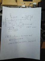
Schematic showing triode as feedback resistance
This shows how a triode is inserted into the DCPP schematic. Half of one channel is shown. Output 6GV5 tube is on the right, input 3CB6 on the left, and the 6SL7 is in the middle on top. Hope it is legible.
This shows how a triode is inserted into the DCPP schematic. Half of one channel is shown. Output 6GV5 tube is on the right, input 3CB6 on the left, and the 6SL7 is in the middle on top. Hope it is legible.
Attachments
Pics please.
jeff
Ditto I wouldn't mind seeing a point to point DCPP. Any shots of the underside of your amp?
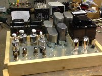
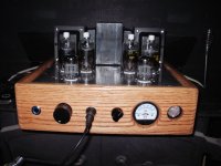
Photos of 12-tube DCPP
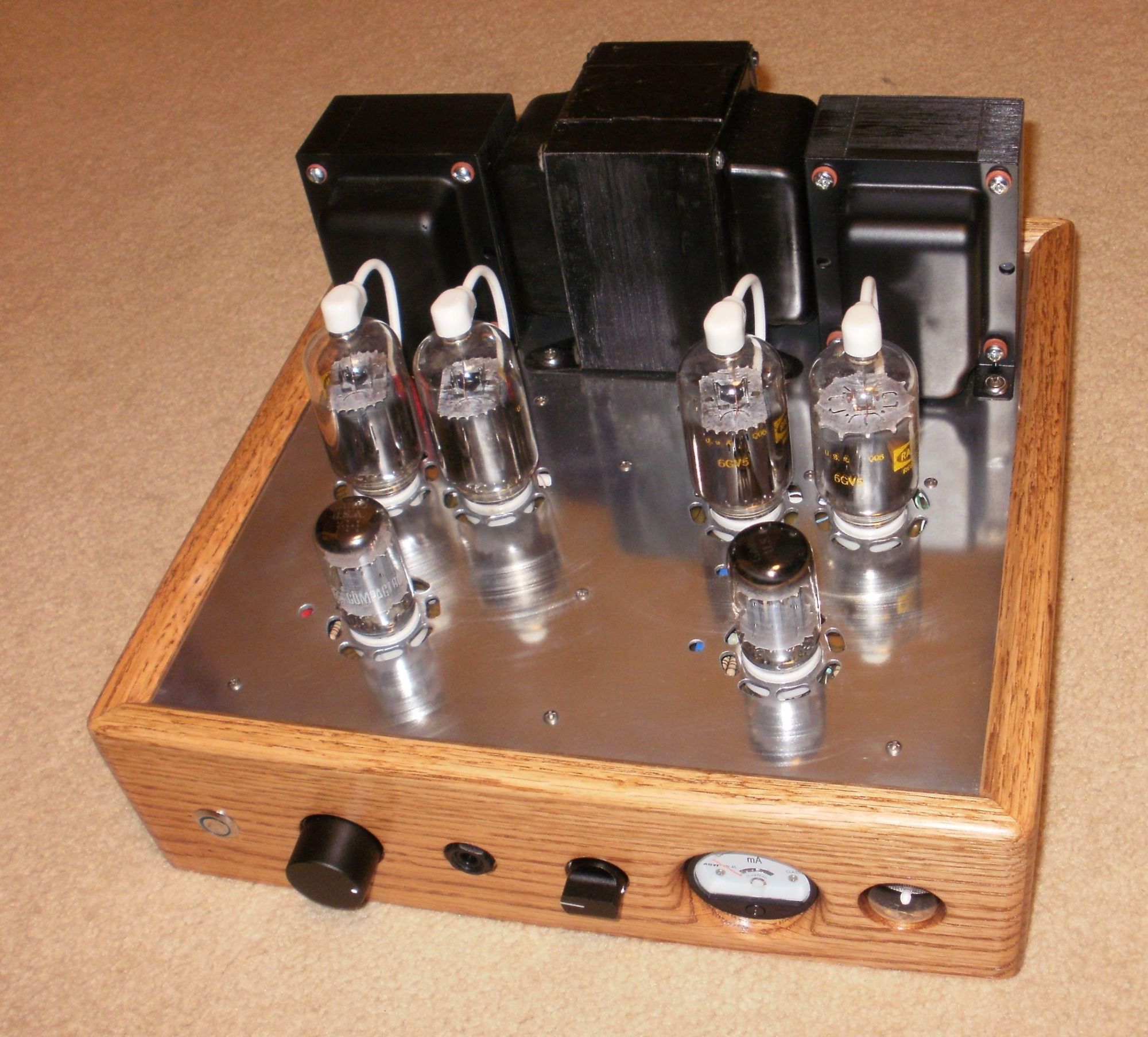
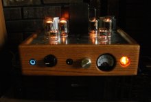
This amp is more of a test-bed at this point. The top plate is an old "no parking" sign that I salvaged from the trash outside of a Fraternity House at the end of a college year. Can't imagine where those boys got a hold of a sign.
The chassis is just a jigged up frame to hold things. Something stylish is yet to come.
I like the throwback industrial look of big motor run caps, big iron and lots of tubes, so that is the way my amps look.
The output transformers are Heathkits, the power transformer a honkin' Philco, and the choke a Hammond I bought 12 years ago.
Attachments
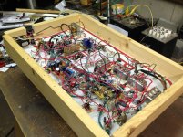
I will try again for photos of the underside. The reflective surface of the chassis plate (the bottom is the old sign front) made the first round of photos unviewable.
Also, when you see the wiring you will realize that I am a hack. It is pretty much a madness of wires. I should have used Pete's board.
Also, when you see the wiring you will realize that I am a hack. It is pretty much a madness of wires. I should have used Pete's board.
Cool looking amp.
The top plates of my two chassis 845SE amp were once an I-69 sign. There were some party animals living in a house two doors down about 30 years ago. I know that at least one of them was a frat boy at Indiana University. When they moved out the new owners tossed the sign in the trash and the trash man wouldn't take it. I decided to see which was tougher, the sign or the Sawsall.
The top plate is an old "no parking" sign that I salvaged from the trash outside of a Fraternity House at the end of a college year. Can't imagine where those boys got a hold of a sign.
The top plates of my two chassis 845SE amp were once an I-69 sign. There were some party animals living in a house two doors down about 30 years ago. I know that at least one of them was a frat boy at Indiana University. When they moved out the new owners tossed the sign in the trash and the trash man wouldn't take it. I decided to see which was tougher, the sign or the Sawsall.
Attachments
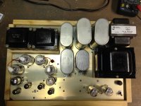
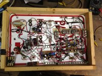
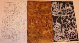
OK, this should either dissuade you from building a DCPP point-to-point, or persuade you that whatever you do it will probably look better than this.
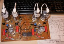
On the top down view, there are four little boards stuffed with stuff. Counterclockwise from the top left, the top left board is the negative power supply (the little transformer too). The circuit board below that (nine o'clock) is a voltage divider network to float the heaters at various VDCs. Below that (6 o'clock) is a circuit board with the screen supply bits plus two of the 30K load resistors for the input tubes. To the right (four o'clock) the biggest board (amidst ten tubes) contains most of the rest of the stuff (grid and cathode circuitry), mostly very close to Pete's design.
On the top down view, there are four little boards stuffed with stuff. Counterclockwise from the top left, the top left board is the negative power supply (the little transformer too). The circuit board below that (nine o'clock) is a voltage divider network to float the heaters at various VDCs. Below that (6 o'clock) is a circuit board with the screen supply bits plus two of the 30K load resistors for the input tubes. To the right (four o'clock) the biggest board (amidst ten tubes) contains most of the rest of the stuff (grid and cathode circuitry), mostly very close to Pete's design.
Attachments
Last edited:
I like the throwback industrial look of big motor run caps, big iron and lots of tubes, so that is the way my amps look.
Wow, there's a lot goin' on there. I like it, but I'd have to build the PS on a separate chassis so I could lift it.
I decided to see which was tougher, the sign or the Sawsall.
Sawsall 1, sign 0.
jeff
I like the throwback industrial look of big motor run caps, big iron and lots of tubes, so that is the way my amps look.
Really cool, makes me want to go ahead with my build. I'm currently really busy writing a thesis in philosophy, but will reward myself by building afterwards. Still a bit stuck on transformer choice though. Let's take a look at those plate characteristics.

You went with aesthetically pleasing too. If I weren't a big person I might not like you.
What are your input tubes? I looked at some of the compactron twin pentodes but didn't think I had found any that had curves close to the 6cb6 class. Not content to use what Pete used I went with 3cb6 (and 4cb6), although they don't seem any cheaper than the 6cb6.
Really, that is a pretty amp. Is it a DCPP or a variant? (Sorry if I should know this by having read this thread, but I have been a little intermittent.)
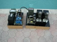
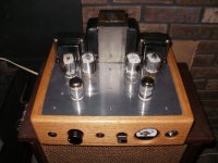
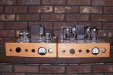
It is a home brewed variant. I used 6U10/6AC10 inputs to have a gain stage followed by LTP to drive the outputs. Schade feedback on the outputs, GNFB also back to the first stage. It all started with 6 6U10 compactrons for $5.00.
I made the first one with 6JN6 tubes to not have any anode caps, Tomiko 35watt output iron, second has 6GV5 and hammond 6.6k 40watt outputs, third is in process with 6LB6/6LF6 tubes and 6.6k 60 watt hammonds.
I made the first one with 6JN6 tubes to not have any anode caps, Tomiko 35watt output iron, second has 6GV5 and hammond 6.6k 40watt outputs, third is in process with 6LB6/6LF6 tubes and 6.6k 60 watt hammonds.
Attachments
i think you should try the 6BH11 also a dollar tube, its a pentode and 2 triodes in an envelope, good for a mulard5-20 topology.....i used this tube in a 6V6 pp amp build.....http://frank.pocnet.net/sheets/123/6/6BH11.pdf
Darn, this is a good amp design! Fired up my monos an hour ago for a little listening before final assembly and I must say that I´m seriously impressed. Smooth but powerful, like an iron fist in a velvet glove...
There is some mechanical buzz from the power transformers that needs some attention but with no signal there is virtually no hum or noise in my very sensitive speakers.
There is some mechanical buzz from the power transformers that needs some attention but with no signal there is virtually no hum or noise in my very sensitive speakers.
- Home
- Amplifiers
- Tubes / Valves
- Posted new P-P power amp design