I understand the differences of pinouts and prepared to deal with that and weird filament volts.
I'm curious as to why the great differences in supposed plate voltage tolerance. I'm sure I'm missing something here and it may be in the footnote with respect to % "on" time, I just don't know...I ask because it seems these "low plate volts" sweep tubes have been operated at much higher voltages in this thread.
I'm curious as to why the great differences in supposed plate voltage tolerance. I'm sure I'm missing something here and it may be in the footnote with respect to % "on" time, I just don't know...I ask because it seems these "low plate volts" sweep tubes have been operated at much higher voltages in this thread.
Last edited:
My experience has been with 6JN6, 6JM6, 6GV5, 17JT6, 6LB6, 6KD6, 6LF6, 6LR6 only.
A couple different B+, 400V and 550V.
What output iron are you using? Ive used 8K-8@25watt, 6.6K output iron @ 40 and 60 watt and 4.3K @60 watt. I like the 1650P 6.6K @60watt iron the best with the 6LR6 tubes at 550V. Next best was the 6.6K output iron @ 40watt with the 6GV5 tubes at 400V. Both great sounding amps. I prefer 6.6K with less feedback, some prefer lower impedance with more feedback..
Asked another way, why the difference and could I run 600 VDC or so on the 6GB5 with no problem?
Sweep tubes were designed to be used as a grid controlled CCS. The constant current is set by the screen voltage and the tube is switched on and off with a square wave on G1. The constant current is switched on through an inductor (the flyback transformer) creating a linear ramp. When the current is switched off a large voltage spike is created in a manner similar to the ignition coil in your car. This why all sweep tubes need a large peak positive plate voltage rating. The tube is cut off during this pulse. Some of this energy is rectified by the damper tube creating a "boosted B+" voltage much higher than the main B+.
They were never intended to work as a linear audio amp. We know otherwise. Most large TV's ran a B+ in the 350 to 400 volt range with boost voltages (the actual plate supply voltage) in the 600 to 700 volt range. This explains the B+ supply ratings of 770 or 990 volts for large sweep tubes.
The 6GB5 and its odd heater voltage relatives were designed for smaller TV sets that used a small power transformer or none at all. The 6GB5 was intended for operation from rectified line voltage with minimum boost voltage since the boost diode was often silicon. The low plate rating is real and we wouldn't think of violating it, right
")
NOT, I have been to 550 volts on the 13GB5. That tube is on the dollar list, so why not.....The issue is not voltage, it is plate dissipation. The tube would probably survive 600 volts on the plate, but it doesn't work well at that level. You need 20+ mA of idle current to eliminate crossover distortion and that uses up most of the dissipation. Cranking up the volume brings the red glow. I haven't had the time to really play with those tubes, but I would guess that the sweet spot is about 450 volts.
Compatron sweep tubes can be found in both 9 and 12 pin versions,
Beware that the 9 pin flavor comes in two different pin sizes too. The Novar has .040 inch pins, while the Magnoval has .050 inch pins. The 6GB5 is a European design and is a Magnoval. You can force them into a cheap Chinese Novar socket, but then you can't use a Novar anymore. It will fall out of the socket.
Good point George, sounds like the Russian 6D22S damper diode, 440ma max but the 9 pins are .047" dia instead of .038" on the US tubes... I've been using 6CG3 to delay switch on the B+, came across some 6D22S for the cheep and got some to play with, need the top cap and 9pin sockets for the big pins. I was thinking of using it on the 6LF6 amp so all of the large tubes would have top caps. IF I run the tubes up to 70ma, I wanted a little more room on the damper diode....
also a dollar tube at Rogalski's the 6CD3 is the king of damper diodes imho.....http://tubedata.tubes.se/sheets/127/6/6CD3.pdf
The 6GB5 and its odd heater voltage relatives were designed for smaller TV sets that used a small power transformer or none at all. The 6GB5 was intended for operation from rectified line voltage with minimum boost voltage since the boost diode was often silicon. The low plate rating is real and we wouldn't think of violating it, right
NOT, I have been to 550 volts on the 13GB5. That tube is on the dollar list, so why not.....The issue is not voltage, it is plate dissipation. The tube would probably survive 600 volts on the plate, but it doesn't work well at that level. You need 20+ mA of idle current to eliminate crossover distortion and that uses up most of the dissipation. Cranking up the volume brings the red glow. I haven't had the time to really play with those tubes, but I would guess that the sweet spot is about 450 volts.
i think that the 6GB5 is sibling to the European EL504 and its heater variant....i am of the impression that they are rather low voltage types and can operate below 100volts....
low voltage operation connotes lower anode loadings, thus design of opt's are much simpler, i have seen a design that use a power traffo for ouput...the PL504 bone shaker amp
Beware that the 9 pin flavor comes in two different pin sizes too. The Novar has .040 inch pins, while the Magnoval has .050 inch pins. The 6GB5 is a European design and is a Magnoval. You can force them into a cheap Chinese Novar socket, but then you can't use a Novar anymore. It will fall out of the socket.
glad you mentioned that, i have issues with the chinese novar sockets, most are loose, so that i have to remove the pins, crimp it some and then reinstall, can not use them as is....
I have put off moving forward with building a chassis for my amp. I have been tossing back and forth on whether to use a pair of 10lb ebay special transformers or else if this pair of Tektronix transformers I have are suitable. The Tek transformer I have has two 113v windings with a DCR of 4ohms each. I used the following formula from forum member Tom Bavis.....
I came out with .7^2 *4=1.96w If that formula works out it looks like I could wire both of those 113v secondaries to create 226v 700ma. I have two of these transformers so I could wire it up in a similar fashion as I did with the pair of 10lbers. Major overkill as they are HUGE but I have given thought to building a universal type power supply. Any reason two of these transformers would have any issue running the 6hj5 variation of this board? I know there is more than enough with regard to the filaments. I have had a hard time finding information pertaining to this specific transformer. It is from a 585 scope. Pete has many of the other transformers listed on his site. There is also a 140v secondary that measures calculates out to around 800ma.
If not, you can measure the DC resistance and allow 2W dissipation for each. So a 10 Ohm winding can handle 450 mA (.45^2 * 10 = 2.02W). Maybe a little more if some windings are left unloaded.
I came out with .7^2 *4=1.96w If that formula works out it looks like I could wire both of those 113v secondaries to create 226v 700ma. I have two of these transformers so I could wire it up in a similar fashion as I did with the pair of 10lbers. Major overkill as they are HUGE but I have given thought to building a universal type power supply. Any reason two of these transformers would have any issue running the 6hj5 variation of this board? I know there is more than enough with regard to the filaments. I have had a hard time finding information pertaining to this specific transformer. It is from a 585 scope. Pete has many of the other transformers listed on his site. There is also a 140v secondary that measures calculates out to around 800ma.
I was hoping that they would be suitable. Considering that I have them on hand it makes using them pretty convenient!Remember, the cool factor goes way up if you use parts you have on hand, and especially if they are salvaged from lab-grade Tek or HP equipment.
It seems that you have a perfect set of iron to make a big, awesome amp!
Is it possible the 275 volts max 6GB5 would be a better pic for the engineers amp as it runs on lower voltage and would not require the boost B+ to the push pull stage?
That's hard to tell. The specs I have for the 6GB5 do not include the plate characteristic charts, so there's no way to draw a loadline to get an idea of how it might perform.
Asked another way, why the difference and could I run 600 VDC or so on the 6GB5 with no problem? I suspect I am missing something here.
These HD power pents are rated very conservatively, given the nature of the intended duty: max RMS power for hours a day, all the while with a reasonable service life. Audio and radio duty (unless it's a "brick on key" mode like FM, SSTV, or packet) are much less demanding.
Another source of confusion here is that the spec for the 6GB5 says "DC Plate Supply Voltage". For the 6BQ6GA, it says: "Boost + DC Power Supply: 600V". These specs refer to two different things. Does it make any difference? Who knows: I have a Portuguese (Brazilian?) design for a ham XMTR that uses 6BQ6GA's, and is running plate voltages of 700Vdc. That, too, is an AM design that isn't constantly developing max RMS power.
In HD service, the 6GB5 will definitely see a plate voltage higher than 275Vdc, due to damper diode boost.
With 6BQ6GAs operating as PP audio finals, Vpp= 350Vdc gave the best performance for distortion, and power output (37W) with some spec busting. Pd= 17W v. the 12W specification for HD duty. Due to the conservative ratings, the finals don't red plate despite the higher plate dissipation, and they've been in operation since 2007.
Sweep tubes were designed to be used as a grid controlled CCS. The constant current is set by the screen voltage and the tube is switched on and off with a square wave on G1. The constant current is switched on through an inductor (the flyback transformer) creating a linear ramp.
Actually a constant current thru an inductor would not cause a linear ramp...
I think this should read: A constant voltage is switched on to an inductor (the flyback transformer primary) thus creating a linear ramp of the current thru this inductor.
So the sweep tube was in fact used as a (lossy) switch with some 50-80 volts left across it when turned on, 150-200 volts on the screen and one amp plate current at the end of the scan line.
The constant current is switched on through an inductor (the flyback transformer) creating a linear ramp........A constant voltage is switched on to an inductor......So the sweep tube was in fact used as a (lossy) switch
In reality all of these explanations are grossly over simplified. The flyback is not an ideal inductor, and it is driving a multitude of circuits including 3 rectifiers with capacitive loads. The flyback circuit is a rather lossy parallel resonant combination that resonates around 200 KHz. It is operated below resonance during trace (somewhat inductive) and rings (well damped) at resonance during retrace. The actual frequency of resonance was adjustable in some 50's color TV with the horizontal efficiency coil. A light bulb was inserted between the plate cap and the flyback and the coil was adjusted for minimum brightness.
An ideal pentode fed by a fixed screen voltage with its grid switched to zero volts would be a CCS. Sweep tubes are far from ideal, the constant G2 curves have a significant upward slope. The control grid drive is not a square wave either, although it was in early black and white TV sets. As tube type color TV's grew in size and the circuits matured there was considerable effort to improve the efficiency of the horizontal sweep circuit. This led to more complex waveforms, but the CURRENT fed through the deflection yoke (not necessarilly the flyback) winding does indeed need to be a linear ramp for both horizontal and vertical sweep.
The actual plate voltage during trace is not constant, and neither is the current. They both start from a low value and rise to a high value at the end of trace.
NOTE: If anyone still has a working tube TV do NOT attempt to measure the plate voltage on the horizontal output tube with either a scope or a voltmeter. The flyback voltage pulse can be several kilovolts with extremely fast rise times and your meter will cease to function as it begins to smoke.
I offer a very simplified explanation because full understanding the operation of a tube type color TV is not simple, nor needed here. The CCS parallel that I often quote is valid to understand why sweep tubes work for screen driven audio amps, and common audio tubes do not.
George, I second NOT measuring flyback voltage. When I was in highschool (ca 1973) I had my dad's Simpson 260 VOM and a HV probe that was probably 20 years old (made of rubber). The insulation had deteriorated so badly that when I hit the anode I flew back (is that where "flyback" comes from?) and embedded the probe in the wall behind me. Lucky I'm still here.
(is that where "flyback" comes from?)
I know about flyback. Lets say I learned from experience.
I went to a technical high school where I learned how to blow up tubes, and sometimes fix TV's. It was 1970, all TV's had tubes, at least any that they would trust to 17 year old kids.
I was poking around in a live TV looking for the reason for no high voltage. I found the burnt spot in the big red wire with my finger which caused immediate flyback. The convergence board blocked my arm's flyback leaving a 2 inch gash. Trip #1 to the ER. An infection ensued, causing a few more trips and eventual surgery. 42 years later there is still a 2 inch scar.
The high voltage supply in a TV rarely kills people, it just causes serious injury from "flyback".
Interesting flyback stories! I wondered why that term was used. I was going to ask about Four thick 3/16 " wires I just got off a huge projection TV being tossed. Just like really good spark plug wires except thinner with red silicone with heavy SS like stranded wire inside. Rated for 50 KV. That must be the Flyback wire? I figured it would be good for top cap anode on tubes like on Pete's Red Engineer's Board?
Thanks!
Randy
Thanks!
Randy
Interesting flyback stories! I wondered why that term was used.
The term actually refers to the way the electron beam is "swept" (that's why they are called sweep tubes) across the TV screen. The beam (making a single dot) is swept across the face of the screen at a controlled rate. It takes roughly 63 microseconds to go across the screen to make a single line. The persistence (afterglow) of the phosphor keeps the line lit long enough for you to see it. The CRT is then cut off while the beam "flies back" to begin another line (about 1 uS). A standard definition picture is made of 525 lines, 480 of which are visible. HD is 720 or 1080 lines.
A linear current ramp is fed to a pair of electromagnetic coils (the deflection yoke) mounted on the outside of the CRT to sweep (bend) the electron beam across the face of the CRT (trace). Once the beam reaches the end of its travel the current is cut off and the beam quickly returns to the start position (retrace).
Very early TV sets used linear amplifiers for both the horizontal and vertical sweep, and a seperate power supply to generate the high voltage for the CRT. Some even used electrostatic deflection much like an oscilloscope.
As TV's got bigger and shallower higher CRT voltages and electromagnetic deflection were needed. The current ramp and cutoff was applied to a "flyback transformer" that functions much like an automotive ignition coil, except additional windings are used to power the magnetic deflection yoke, the focus rectifier and generate timing pulses for several circuits.
The term "flyback" was held over into the SMPS (Switch Mode Power Supply) world since there is a class of SMPS that functions in the same manner.
Super Newbie
First post on diyaudio.
Background: I have a master's in aerospace engineering because I liked aircraft and spacecraft just slightly more than electronics, but I gotta tell you, I love electronics, diy projects, and design. Of course I've had a few electrical courses in school, but that was a while back, so it's all still fuzzy. I can read a basic schematic, but every once and a while there is a symbol that baffles me until Google saves the day. I've had my instrumentation coursework for measuring, analyzing, and breadboarding projects. I used to build my own battery packs for R/C cars back when they were still Ni-Cads and Ni-MH, so I have some iron work, but imagine it'll take a more subtle approach for board work.
How'd I end up here: I read many gadget blogs and design blogs instead of "real news" and a couple times saw articles about tube amps and some of the designs and thought they look so beautiful. I loved the idea of combining, DIY, electronics, design, and some retro devices into a beautiful object, so I went for it. I have yet to put solder to the board, but I'm starting with a Millet MOSFET Max for my headphones at work. I'm the type of person who dives headfirst into a project, and so I've already ordered my board for my "Engineer's Amplifier", which should suit me well. BTW - Thanks Mr. Millett for the very fast shipping of the board I ordered not more than four/five hours ago.
Anyway, here I am. No questions just yet, mostly just reading through the hundreds of posts, the numerous articles about amps in general, classes of amps, types of tubes, types of amplification schematics, and getting out my old electrical engineering books (glad I kept all those school text books). I'm sure I'll have questions. Looking forward to my first of what I hope will be many amp projects.
Thanks,
Ben
Welcome Ben
I have made a couple of Pete's amps, including this one and have another on the go!
I like them because the are sort of real world and almost a working mans project. Also Pete has always answered the few questions I have emailed him very quickly, great guy.
You wont go far wrong here, tried and tested
Dagwood
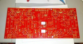
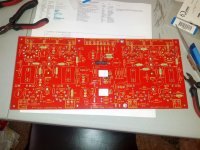
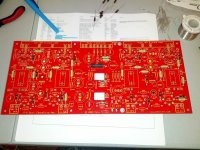
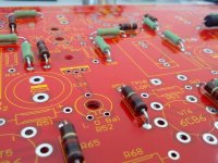
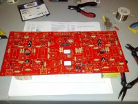
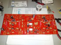
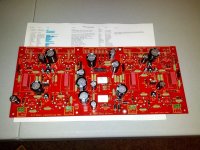
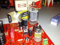
Work is progressing rather nicely. Got my big red board the other day, and then my mouser order as well. Still have a few things to order, such as the tube sockets. My Edcor order has been placed, but no word on lead time yet, so we'll see. This was a blast! Using a bit of imagination in the last photo. Got a few 6GV5 sweep tubes for $1 each and some 6DK6 tubes for $.75 each, so I'm gonna try those first.
Attachments
-
 IMG_20120909_124101.jpg221.2 KB · Views: 691
 -
 IMG_20120909_131918.jpg177.2 KB · Views: 680
 -
 IMG_20120909_160321.jpg182.2 KB · Views: 675
 -
 IMG_20120909_160954.jpg115.6 KB · Views: 677
 -
 IMG_20120909_172915.jpg166.9 KB · Views: 668
 -
 IMG_20120909_175315.jpg174.1 KB · Views: 166
 -
 IMG_20120909_194413.jpg157.7 KB · Views: 204
 -
 IMG_20120909_194921.jpg169.7 KB · Views: 290
- Home
- Amplifiers
- Tubes / Valves
- Posted new P-P power amp design