revintage said:
Someone else can do that! Just joking, will do a sim for you when I get home from work.
MJK, do you have any ideas of what value the two "source" resistors in the triode-antitriode configuration ideally should be? Reread the thread and found you presented the constantvoltage version already at page one.
My main concern is if the internal caps of the DN2540 really shows up on the sims? I use the Supertex Spice model.
But at the moment my own interest is to find an "el cheapo" sand-replacement for an anodechoke.
So a totem pole circuit is indicated.
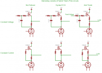
Here are all the variations I can think of right now, ignoring
for the moment the common anode circuits. For each of
constant current, constant voltage there are 3 basic modes:
1. "Mu-Follower" with very low impedance and current source
capability. I like this mode for driving a power grid tube in
class A2 or AB2. The triode operates on a flat load line.
2. "Gyrator" simulates an inductor. Can source current into the
load approaching Iq. The triode will "see" 100% of the load.
3. Anti-Triode is meant to drive a load such as a loudspeaker
or 600 ohm line input, where symmetric drive, low impedance,
2X idle current drive capability, and power supply efficiency are
desired. The triode and MOSFET equally share the load 50/50.
The resistor values for the anti-triode might be optimally chosen
to be different by a factor of 1/gm of the MOSFET, but in practice
I don't think it matters much.
I would simulate the anti-triode circuit as a parafeed output stage
in comparison to choke-parafeed and CCS-parafeed. The Anti-Triode
will have 1/2 the Zout though, so I would adjust the load accordingly.
Perhaps it should be compared with PSE, as it produces equivalent
outpower and has equivalent Rp
The AT circuit seems to work well with damping factors ~4 and above
IRL.
In summary, for grid drive I would try the mu-follower, for choke
substitution the gyrator, and for a line driver or output stage I
would use Anti-Triode mode.
Cheers,
Michael
PS I excluded the common-anode variants (hybrid-super-cathode-followers)
but there are three variations having different drive characteristics
as well.
Attachments
Hi Michel,
So now you got six alternatives !
There are a few of them to eliminate. Lets stick to what Salas asked for. Think it was about preamp output. Wich ones would you consider?
Kenpeter,
Remade the the tests at 1kohm load. Not so much more impressing with the triode anti-triode, even if it was slightly better.
So now you got six alternatives
!There are a few of them to eliminate. Lets stick to what Salas asked for. Think it was about preamp output. Wich ones would you consider?
Kenpeter,
Remade the the tests at 1kohm load. Not so much more impressing with the triode anti-triode, even if it was slightly better.
Salas said:Hi guys
I have made a couple of variable anode CCS sources. One cascode enhancement Mosfet LED biased of mine, and one Jung's LM317 10M45S cascoded. I am running experiments on my 6V6 trioded line pre. My B+ is 330V regulated and there is a capacitor bypassed 680R cathode resistor installed. I measured much better THD at the same bias point where the previous 5K resistive load was sitting (22mA). Sounded dynamic and clean, but in the long run I miss the previous tamer but more natural tone. It got more SS taste, and it got a bit of more hiss on my 95db speakers. When I took it down to 15mA, it backed up on hiss and SS tone, but still the same impressions. I wanna retain the dynamic and THD gains, but bring back some triode tone. I guess that valves can be pushed a bit with anode CCS and hiss if not lower current than previously with resistor is chosen? OK, the Mu is pushed now, but I have got more hiss compared to gain.
It reminded me of when running a noval hotter until it starts to simply hiss. Anyway, that is why I wanna listen to the Anti-triode before I go back to resistor loading. How it can be practically done best? I mean, just put two resistors between CCS and anode, and tap off from the center for output? OK then, is there a formula to calculate, given the B+, freely chosen CCS current, and given Rk as I described above?
EDIT: Here is the chart of 6V6 trioded. Suggestions for anti-triode?
The hiss is an indication of RF oscillation. It is a frequent problem
with CCS or MOSFET use, but should be able to be eliminated
through short wires, gate and grid stoppers, etc. Normal random
noise levels should be practically inaudible in a line stage, assuming
reasonable gain/level structure.
I'm not sure, however, if anti-triode will give you back the triode
tone you seek in a line amp. The resistor is probably best for that.
I think of a steep load line with some asymmetry in the swing.
Using either a mu-follower or anti-triode will flatten the load line
even more than the gyrator, resulting in less even harmonic distortion
and less triode tone. There might even be more higher order
distortion evident with the flatter load line (especially assuming
6S45pi).
If you do want to try a "real" anti-triode SEPP circuit, I think
the anti-triode operation pretty much depends on nearly equal
resistance either side of the tap. Either the constant voltage or
constant current anti-triode circuit would work. For CC, set the total
resistance as you would a CCS current set resistor. For CV, I would
start with something that gives about 2V total drop at idle and
maybe tune by ear. As ken mentions, CV does not require a d-mode
device.
Cheers,
Michael
I just thought of a reason the constant voltage circuits might sound
different from the constant current ones.
It has to do with the average current shift that occurs in a nonlinear
(e.g.triode) power amplifier at large signal conditions.
A constant current load responds to this by reducing the anode
voltage at large signal conditions such that the average current is the
same as the idle current. This is in effect a compressor, as reducing
the anode voltage will lower the gain under most conditions.
The constant voltage circuits (Wavebourne, gyrator, CV above...),
on the other hand, may have a more linear dynamic response
due to the average current being allowed to increase as signal swing
increases, at a constant average anode voltage.
I don't know how large the effect may be, but it may be a good reason
to try both.
Michael
So, how many kits to prepare?
I'm going to order PCBs for 2 types of gyrators: like mine from a mic preamp (cascoded), but more flexible, for adjustable voltage drop and different power dissipations (like to load 6V6), and one with 1-FET like Michael suggested.
The price per PCB will highly depend on the number of them I order.
I'm going to order PCBs for 2 types of gyrators: like mine from a mic preamp (cascoded), but more flexible, for adjustable voltage drop and different power dissipations (like to load 6V6), and one with 1-FET like Michael suggested.
The price per PCB will highly depend on the number of them I order.
As ken mentions, CV does not require a d-mode
Once again, what´s wrong with depletion mode?
Think I´ll make an IRL test with the one-transistor circuit I showed earlier. Will try two versions: 2SK2700 and DN2540.
Will also come back with a simmed comparision between IRF610 and DN2540.
Did some PSRR sims yesterday and it seems like the N-channel versions are better.
The constant voltage circuits (Wavebourne, gyrator, CV above...),on the other hand, may have a more linear dynamic response
due to the average current being allowed to increase as signal swing
increases, at a constant average anode voltage.
In other words, the CV lets the triode breathe easier.
revintage said:
Once again, what´s wrong with depletion mode?
Think I´ll make an IRL test with the one-transistor circuit I showed earlier. Will try two versions: 2SK2700 and DN2540.
Will also come back with a simmed comparision between IRF610 and DN2540.
Did some PSRR sims yesterday and it seems like the N-channel versions are better.
In other words, the CV lets the triode breathe easier.
Hi Lars,
I don't think there's anything wrong with d-mode devices; in fact,
I rather like the way the DN2540 transfer curve plays against triodes
from 0-100mA. The gfs increases as the current increases,
perhaps compensating for the gm decrease of the tube at low current
in anti-triode mode.
I would try a DN2540 against a 1N60 to see if either one sounds
better. I also like the idea of the DN2540 as the constant voltage
device in a cascode controlling an IGBT etc. I have a bag of them in
TO-92. I also have a bag of 2N7000s...
Interesting analogy; the triode breathes easier... I also think of CV
mode not cutting the triode any slack on the peaks; makes it work
a little harder.
Michael
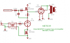
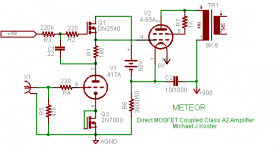
Direct MOSFET Drive (DMD)
Excellent!
If you use Mu-follower mode, you can drive some grid current,
as in this amp I'm currently breadboarding (simplified schematic...)
Cheers,
Michael
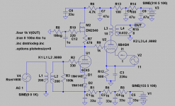
revintage said:This is an idea of a DC-coupled SE with gyrator-loaded driver.
Instead of DN2540, 2SK216 could be used. IRF610 is not recommended due to its high capacitance.
Excellent!
If you use Mu-follower mode, you can drive some grid current,
as in this amp I'm currently breadboarding (simplified schematic...)
Cheers,
Michael
Attachments
Simple, w/o input transfomer and negative rail. R12 dissipates over 12W though.
Michael,
Your amp is not far from the 813 SE circuit I have been working on. Can not decide wheter going PP or SE. However, I will not go A2 so I skip the sand-follower. Guess 4-65A could be looked upon as 813s little brother. Found Slagles 4-65 triode curves at AA.
Michael,
Your amp is not far from the 813 SE circuit I have been working on. Can not decide wheter going PP or SE. However, I will not go A2 so I skip the sand-follower. Guess 4-65A could be looked upon as 813s little brother. Found Slagles 4-65 triode curves at AA.
Attachments
Class A2 Hybrid Monkey
But if you did want A2 operation, using MOSFET drive allows you to
implement a class A2 Hybrid Monkey.
I'm thinking about trying single supply operation as well, by using a
floating supply for the grid drive returned to the cathode. All the grid
current thus stays in the local loop and doesn't affect voltage across
R6.
I'm using Slagle's curves also. I think the 4-65A looks pretty linear
but you need A2 to get good efficiency with these.
I also want to try anode-anode feedback in pentode mode using
a D3A pentode driver, but that's another story.
Michael
Attachments
I don't know about an unbypassed CCS below the cathode?
Regardless of plate load, how can that work? I suppose as
long as your plate load keeps you underneath the CCS limit,
its a bit of a do-nothing.... But then what voltage is Bias?
I would think with fixed anode voltage, you would want LED
for the cathode, and let quiescent current fall where it may....
Or is your anode voltage not fixed, only the top end of the
current sense resistor? Is the voltage drop from here (seen
at the plate) intended to be the variable to change with age?
Again, I'm not sure how even this can vary when you got an
unbypassed CCS in the cathode current path?
When nailing down multiple parameters, watch out for those
that might have a tendency to fight each other.
Hi Ken,
I'm guessing that you're referring to the 2N7000 in the cathode
branch of the driver circuit.
I have it arranged as a constant voltage device, with the gate wired to
the drain. I have found this to be a stable self-bias method that
drops 2.7 V at 20mA and has a dynamic resistance of about 7 ohms.
It's dead quiet also.
I really need 3 volts so will probably add a schottky diode as well.
I also left off the gate protection zeners, etc. to simplify the concept.
Michael
PS I thought of an advantage in using an enhancement mode FET
instead of a depletion mode device; you only need a single zener
diode for Vgs protection as opposed to back-to-back.
OK, I see it now... 2N Gate to Drain strappage... Constant voltage.
Now I got a strange unity buffer sand output stage I been working on.
Pair of Alephs abused against each other in wierd and unusual ways
(Like act all surprised that I would design something weird)...
Anyways, the pre-amp section is a pentode, with voltage centering
anti-triode (center tapped active load). Voltage centering would
give ambiguous current against plate impedance of such a pentode,
except what I did with the screen feedback was also very unusual.
I got 2K2 screen resistor pulled up to the mu follower (top source
node of the anti-triode totem), and cap coupled to watch the final
output of the unity buffer. Both of these signals are followers of
the plate to some extent. Thus pseudotriode strapped, indirectly...
And plate (and screen) currents I hope following rule of triodes.
Trying to keep the tube in the loop, and at least partly aware of
the real load. At least the sceen should be fully aware anyways...
I'm not where I can draw you a schematic right now.
Wavebourn said:If you want more PSRR on frequencies below than a current source provides I can add an active filter or even a voltage regulator on top.
One that can be jumpered in or out of circuit would be nice.
Wavebourn said:So, how many kits to prepare?
I'm going to order PCBs for 2 types of gyrators: like mine from a mic preamp (cascoded), but more flexible, for adjustable voltage drop and different power dissipations (like to load 6V6), and one with 1-FET like Michael suggested.The price per PCB will highly depend on the number of them I order.
I'm interested in both but more in your original.
I'm working on a project with some odd unknown tubes (no data sheets or nuthin) that will take some time to find the best op point for. These WACHIS (Wavebourn AC High Impedance Sources) with trimmer would be terrific together with a pot as Rk for dialing in the best spot. If you're thinking of doing them soon I'd be in for a few pairs. Time to move to market place???!!! _

resurrection
I found this thread casually interesting the first time through, but now that I've built a circuit found here, I'm really interested.
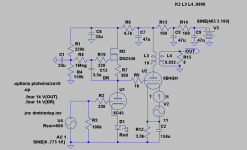
The attached schematic section is part of a phono amp described here: http://www.diyaudio.com/forums/tubes-valves/169428-unholy-alliance-phono-amp.html
I built a cascoded mu follower gyrator, along the lines of Michael's suggestions in the latter part of the this thread. It seems to work fine, but one aspect has me completely stumped. Michael uses a low value feedback (bootstrap?) resistor, to maintain a constant charge across the source resistor. However, this cap value needs to be much higher in my hands, and seems related to the plate resistance of the tube it loads. Something along the same lines is noted by Lars in page 5 and 6 of the thread, as it pertains to Wavebourn's circuit and the low frequency pole. I didn't understand the calculation then, and don't now - though I've stared at it for some time. It's seems obviously related to feedback to the gate of the control device, but I don't know how this is calculated. Any clues appreciated.
Sheldon
I found this thread casually interesting the first time through, but now that I've built a circuit found here, I'm really interested.
The attached schematic section is part of a phono amp described here: http://www.diyaudio.com/forums/tubes-valves/169428-unholy-alliance-phono-amp.html
I built a cascoded mu follower gyrator, along the lines of Michael's suggestions in the latter part of the this thread. It seems to work fine, but one aspect has me completely stumped. Michael uses a low value feedback (bootstrap?) resistor, to maintain a constant charge across the source resistor. However, this cap value needs to be much higher in my hands, and seems related to the plate resistance of the tube it loads. Something along the same lines is noted by Lars in page 5 and 6 of the thread, as it pertains to Wavebourn's circuit and the low frequency pole. I didn't understand the calculation then, and don't now - though I've stared at it for some time. It's seems obviously related to feedback to the gate of the control device, but I don't know how this is calculated. Any clues appreciated.
Sheldon
Attachments
Last edited:
MOSFET source, MOSFET gate, and and FET hopefully follow the Triode's plate.
We should never see the FET's RC constant. But one might still see FET Miller if
the MOSFET above tracks poorly due to its own Miller... Then this error drives
from FET source back into MOSFET gate to slightly compound itself.
We have FET gate cap driven by 8.2uF in series with 1K and plate resistance,
but corner frequency is not so clearly related because of all the bootstrappage
goin' on. We don't really know what gate cap dynamically is? Or maybe I don't
understand the question?
I'm not offering easy answer, just sayin' I do see why this might be confusificatin.
My head hurts just looking at it! Sim should be accurate so long as the MOSFET
drain holds 10 or more volts in reserve to keep the channel shape from changing.
If the channel shape relaxes too much, the Miller cap becomes big like the gate
to source, we don't want that...
Last edited:
Thanks for the reply.
I don't think the gate capacitances are the issue. At least, that's not where I was going with this. It shouldn't take much capacitance to overwhelm the FET capacitance - I wouldn't think anyway.
I was looking at the plate end of the bootstrap cap as a low impedance node to common - at least relative to the 1M supply resistor. But if I use a low value cap, say 100nf, the low end starts rolling of in the low hundreds of Hz. Seems consistent with the RC constant being derived from bootstrap cap and the plate resistance of about 9K for this case. Lars also mentioned the tube impedance as the main factor in calculating this cap, but I don't know how that's derived. Also, Michael's examples use low value caps. But if those values work, then I'm way off or missing something. Makes my head hurt.
Sheldon
- Status
- This old topic is closed. If you want to reopen this topic, contact a moderator using the "Report Post" button.
- Home
- Amplifiers
- Tubes / Valves
- Anti-Triode SEPP, how to do best?