Hello,
Connecting windings like that is one way to include cathode feedback. But for DC current compensation it does not work because for proper magnetic cancellation the current in the secondary winding should be approksimately the same as primary current times winding ratio, which condition is not fullfilled in this.
Doing this way can reduce the distortion though and thus is interesting.
- Elias
jerluwoo said:Have you tried simply grounding the cathode through the secondary so that you have the same amount of dc through primary and secondary? Curious if this would have a cancelling effect on saturation or not.
Connecting windings like that is one way to include cathode feedback. But for DC current compensation it does not work because for proper magnetic cancellation the current in the secondary winding should be approksimately the same as primary current times winding ratio, which condition is not fullfilled in this.
Doing this way can reduce the distortion though and thus is interesting.
- Elias
Hello,
Well, cannot say it didn't come to my mind doing PP. But as far as I understand PP operation, it cancels even order distortion and what is left is nasty odd order. Exactly the opposite I'd like to achieve! I want to find out how an amplifier with dominating even order distortion sounds like. That's why my primary interest is SE at the moment.
- Elias
john_ellis said:
I don't think transformers like to be treated the way you supposed. If you are going to the trouble of adding a compensating DC current, why not operate two valves in Class A push-pull?
Well, cannot say it didn't come to my mind doing PP. But as far as I understand PP operation, it cancels even order distortion and what is left is nasty odd order. Exactly the opposite I'd like to achieve! I want to find out how an amplifier with dominating even order distortion sounds like. That's why my primary interest is SE at the moment.
- Elias
Hello,
I agree, DC compensation is essential to makes toroids to work.
How do you implement CCsink in the cathode, do you mean in SE as well, or in PP? In PP I can understand cathode current balance being important but does CCS bring any benefit in SE?
Great to hear you have a lot of experience with toroids. And yes I think also toroids are a great potential!
- Elias
Shoog said:... However I think the whole idea of SE toroidals is a big mistake and wouldn't recommend it at all. Having said that, DC compensation would seem to be the way to go. If I did that I would put a CCSink in the cathode to make it rock solid stable over time. Basically choke loads are expensive and introduce all of the nasties which toroidals avoid - so no advantage and no cost saving.
I have three amps using toroidals in PP amps and this is where they shine the most. Response down to 10Hz and up to 60kHz. DC balance is essential and can be achieved with CCsinks in the cathodes, or with "Garter Bias". I like to get my CCS to within 1mA, bass suffers badly after that. LM317's make reasonable candidates for CCS. One thing to watch is because of their extreme bandwidth they do tend to ring and may need dummy loads. ...
I agree, DC compensation is essential to makes toroids to work.
How do you implement CCsink in the cathode, do you mean in SE as well, or in PP? In PP I can understand cathode current balance being important but does CCS bring any benefit in SE?
Shoog said:My personal experience of using toroidals is with
- 6080's running at 100V 100ma, very low output impedance.
- ECL82 with plate to plate feedback which reduces output impedance down to CF levels.
- 807 with plate to plate feedback as well.
...
However I believe Steve Bench made his Matrix amps with toroidals as outputs and he measured very high inductances and very good results. I think experience is stacking up to show that they work well and work well down to very low frequencies - better than many SE transformers.
Great to hear you have a lot of experience with toroids. And yes I think also toroids are a great potential!
- Elias
Re: Re: Using mains transformer as output transformer
Hello,
Ok. I didn't measure inductance yet. If it's too low EL34 does not seem to care about it, since signal goes much less than 20Hz and it's quite clean. However, can be that this toroid has enough high primary inductance for proper impedance transformation also at low freqs. Measurements will show eventually.
- Elias
Hello,
Merlinb said:
That depends mainly on the primary inductance. If you want any bass at all you should be looking for the highest primary inductance you can get.
Cheap toroids may have less than 1 Henry, which is useless. You might get lucky and find one with around 10 Henrys, which would be "useable" for lo-fi applications using pentodes (such as a guitar amp or radio), but if you want to get anything that remotely looks like hifi you''ll have to use it with a low impedance valve, like a nice beefy triode. Couple of triode-strapped ECL86s maybe.
Ok. I didn't measure inductance yet. If it's too low EL34 does not seem to care about it, since signal goes much less than 20Hz and it's quite clean. However, can be that this toroid has enough high primary inductance for proper impedance transformation also at low freqs. Measurements will show eventually.
- Elias
Hello,
Thanks") Currently I have only the output stage on the table. I need to make a driver as well. At this point I'm investigating different options to use a toroid at the output. One day this is will turn out to be a whole amplifier I'm sure
Currently I have only the output stage on the table. I need to make a driver as well. At this point I'm investigating different options to use a toroid at the output. One day this is will turn out to be a whole amplifier I'm sure
Interesting, two people using totally different size of transformers. Regarding the high freq roll of, which size toroid has wider bandwidth in the top, big or small VA ratings? Any rule of thumb in this?
- Elias
316a said:
Well done ! Are you going to share the design ? I'm surprised at your upper rolloff . I got -0.5dB down at 20khz using a 6B4G into a 230:9+9 Talema 30VA unit .
Thanks
Currently I have only the output stage on the table. I need to make a driver as well. At this point I'm investigating different options to use a toroid at the output. One day this is will turn out to be a whole amplifier I'm sure Shoog said:I use at least 150VA units for my output transformers.
Interesting, two people using totally different size of transformers. Regarding the high freq roll of, which size toroid has wider bandwidth in the top, big or small VA ratings? Any rule of thumb in this?
- Elias
I'm about to start back in on these Toroids late next month with my home wound 350VA tranny as parafeed. Class A2 SE with GU48, ex computer 10V heater psu, MOT as choke. Solid state transformer coupled drive with positive Vg. HT still undecided but preferably much less than 850V.
Keep up the good work.
Mike
Keep up the good work.
Mike
The bigger transformer will suffer most - but my experience is that it just doesn't matter. In theory the smaller VA will have higher primary inductance. I prefer the greater immunity to saturation offered by the bigger transformer.Interesting, two people using totally different size of transformers. Regarding the high freq roll of, which size toroid has wider bandwidth in the top, big or small VA ratings? Any rule of thumb in this?
How do you implement CCsink in the cathode, do you mean in SE as well, or in PP? In PP I can understand cathode current balance being important but does CCS bring any benefit in SE?
I did put a CCS in the cathode of an SE amp but it didn't make any significant difference to the sound. What I was suggesting was putting a simple CCS in the cathode when using DC compensation. My thinking is that it will lock the arrangement into stable current through the valve even when the valve ages. This will make the transformer immune to saturation under most conditions.
I'm about to start back in on these Toroids late next month with my home wound 350VA tranny as parafeed. Class A2 SE with GU48, ex computer 10V heater psu, MOT as choke. Solid state transformer coupled drive with positive Vg. HT still undecided but preferably much less than 850V.
Keep up the good work.
Mike
I tried a MOT transformer on a RH807 SE design. It worked, but when comparing it to other amps it seemed to show phase shift issues. I think this is because though the inductance of the MOT is enough to make it work, it isn't enough to dominate the arrangement. Most parafeed choke loads seem to have inductances well over 50Henries, the MOT can probably only manage something around ten. I had it set up before with a pentode CCS and this seemed to work better.
Shoog
By the way, excuse my ignorance but what is CCS (Constant Current Source?) This appears to be referred to continuosly in posts. Pls direct me to any source material.
Because my Toroid was made for a PP amp and it also has seperate UL windings, any of these could be used for balancing the Ia in an SE setup. Also any extra secondary winding could be added for this purpose. How should signal voltage on this winding be treated seeing as it also presents a load to the tube?
Regs
Mike.
Hello,
quote:
Originally posted by jerluwoo
Have you tried simply grounding the cathode through the secondary so that you have the same amount of dc through primary and secondary? Curious if this would have a cancelling effect on saturation or not.
Connecting windings like that is one way to include cathode feedback. But for DC current compensation it does not work because for proper magnetic cancellation the current in the secondary winding should be approksimately the same as primary current times winding ratio, which condition is not fullfilled in this.
Doing this way can reduce the distortion though and thus is interesting.
- Elias
Thanks for the reply Elias. I was curious since this is how my EL84 SE amp is built and it sounds great. It has standard gapped output transformers though. Thought it might make it easier to use a standard transformer.
Hello,
It's best to feed the conpensation current from current source instead from voltage source. By definition current source has very high output impedance thus it's loading to the primary side will be minimised.
I was trying to do current source from LM317 and LM337, but with transformer as a load they were unstable and I couldn't tame the oscillation in a reasonable time so I throw them aside and made simple current source from darlington transistor, LED and trimmer. Works nice and seems to be good enough for the purpose. And no stability issues!
- Elias
boiss said:However putting on another secondary winding and pushing several amps down it to balance the flux in the core fixes the DC problem but what about the loading of the AC signal that would now find itself with the DC bias supply impedance across this secondary winding?
Hej Elias,
Your project is very interesting. This is something I must try.
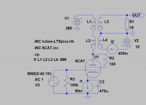
Did a sim and schematic of it. Hope I understood your idea right.
When calculating turns/voltage ratio you should measure unloaded voltage at the secondary.
Also with 8ohms load on EL34 in your prototype you are loading it a little to hard, 16ohms will a more appropriate loading in the ballpark of 3k depending on unloaded secondary voltage.
To use a 6B4G like 316a did, would be even better. But not at all as cost efficient . For 8ohms load 12V, like you said in your first post, would be more efficient with any of the tubes. A typical 50VA has a secondary of 13,7V and this corresponds to 2300:8ohms.
Brgds
Your project is very interesting. This is something I must try
.Did a sim and schematic of it. Hope I understood your idea right.
When calculating turns/voltage ratio you should measure unloaded voltage at the secondary.
Also with 8ohms load on EL34 in your prototype you are loading it a little to hard, 16ohms will a more appropriate loading in the ballpark of 3k depending on unloaded secondary voltage.
To use a 6B4G like 316a did, would be even better. But not at all as cost efficient
. For 8ohms load 12V, like you said in your first post, would be more efficient with any of the tubes. A typical 50VA has a secondary of 13,7V and this corresponds to 2300:8ohms.Brgds
Attachments
Hello,
I see what you mean. Earlier I was thinking using active DC tracking for compensation current, but using CCS at cathode as you propose may be easier to do.
One thing I'm not so sure about is how much tube bias current changes during time with tube ageing let's say after couple of years of usage? 'Depends on the tube' I suppose would be the answer. Knowing this would help to decide do I need tracking compensation or not. Of course I could manually tune compensation once and a while but that's not a very elegant solution is it
- Elias
Shoog said:I did put a CCS in the cathode of an SE amp but it didn't make any significant difference to the sound. What I was suggesting was putting a simple CCS in the cathode when using DC compensation. My thinking is that it will lock the arrangement into stable current through the valve even when the valve ages. This will make the transformer immune to saturation under most conditions.
I see what you mean. Earlier I was thinking using active DC tracking for compensation current, but using CCS at cathode as you propose may be easier to do.
One thing I'm not so sure about is how much tube bias current changes during time with tube ageing let's say after couple of years of usage? 'Depends on the tube' I suppose would be the answer. Knowing this would help to decide do I need tracking compensation or not. Of course I could manually tune compensation once and a while but that's not a very elegant solution is it
- Elias
Hello,
You are right, 8ohm load at 16V secondary is a bit too heavy load for EL34 and I cannot quite get the power I want out of that tube. Now the distorsion steps in too early.
With this set up I can get about 2W quite pure power. I'll investigate more with different kinds of feedbacks also to find the optimum.
Also increasing +B from 280V would help to get more power I suppose.
Anyway, I've been thinking to wind an extra coil on the toroid for the load let's say something between 9-12V. In theory it should improve things.
- Elias
revintage said:...Also with 8ohms load on EL34 in your prototype you are loading it a little to hard, 16ohms will a more appropriate loading in the ballpark of 3k depending on unloaded secondary voltage.
To use a 6B4G like 316a did, would be even better. But not at all as cost efficient
You are right, 8ohm load at 16V secondary is a bit too heavy load for EL34 and I cannot quite get the power I want out of that tube. Now the distorsion steps in too early.
With this set up I can get about 2W quite pure power. I'll investigate more with different kinds of feedbacks also to find the optimum.
Also increasing +B from 280V would help to get more power I suppose.
Anyway, I've been thinking to wind an extra coil on the toroid for the load let's say something between 9-12V. In theory it should improve things.
- Elias
One thing I'm not so sure about is how much tube bias current changes during time with tube ageing let's say after couple of years of usage? 'Depends on the tube' I suppose would be the answer. Knowing this would help to decide do I need tracking compensation or not. Of course I could manually tune compensation once and a while but that's not a very elegant solution is it
Not very elegant at all.
This is the main reason I started using cathode CCS to save constant adjustment. I feel certain that this compromises the sound a little, but I really do not want to be fiddling all the time and am willing to pay the price. The benefit I get as a side line is that I can configure the output pair as a differential amp which improves the sound detail over bypassing to ground.
With my 6080 PP amp everything stays in adjustment for about a year (use of about 12hrs per day), and then eventually they start to oscillate as the CCS can no longer take up the slack. Its a good indicator that its time to change the 6080's.
Shoog
Hmm, This CCS thing using for example a 7805 and an O/P transistor would also have to handle the O/P signal voltage on the winding which is unloaded (High Z). Need to work this out with a clear head methinks. How many people running over 20W have cooked their I sources?
Running a comparable to Ra winding in the K to -Ve rail would cause severe negative FB unless it was heavily decoupled or the drive was strictly between G1 and K, bias included. I guess that the way to go has to be transformer interstage coupling for this system to work in order to avoid neg FB along with heavy decoupling to ground note not the -Ve rail.
Using other small secondary windings in the K circuit would do little to null the standing I in the toroid but would add varying amounts of NFB.
hope this makes some sort of sense!
Cheers
Mike.
Probably got it all wrong as usual!!!
- Home
- Amplifiers
- Tubes / Valves
- Using mains transformer as output transformer