Still probs with this schematic
The previous version couldn't pull down far enough to starve
any but the highest Mu plate. Even that one, not completely...
Anyways, I'm still at it. I could just multiply the plate current
of a triode (same as with the diode on the right) and have a
quick and easy solution. But why do things the easy way?
I found that I could get away with two diodes, if I blend the
lower Mu in at a higher transconductance. The curves blend
seamlessly without any kink... And we get just a slight bit o
the old lean to the right. Not too much!
I still got a bunch of problems to work out before this circuit
has any chance of functioning. But I done another set of fake
curves to illustrate the kinkless blending.
Attachments
I'm not afraid to try something new, but I think the next step for me is scaling this idea up a little and using a linear tube. I want to explore the sonic potential of this in a practical HiFi amp.
How about 16 watts from a SE 2A3 with a damping factor of >6 ? With 4X current boost the 2A3 can play into a 5K load for a very linear load line. The "anode" efficiency is about 30% in this case; 16 watts Po from 52 watts B+.
This is something I already have the parts for. I thought I would add another piece of sand or 3 to the driver as well after perusing the tubelab.com site.
Using a MOSFET voltage follower allows me to build a 2 stage amp with more gain and linearity in the first stage, and use what I consider to be a great sounding tube, while providing good drive to the output tube.
Actually I guess it's a 3 stage amp if you count current gain as a stage... Anyway I was thinking of a DC choke coupled design and decided to give DC + MOSFET coupling a try.
This way if I get a loose socket pin in the driver I blow up not only the 2A3 but a couple of $10 MOSFETS also. I will use a fuse to protect my UTC iron, though.
Cheers,
Michael
Just ran into your post last night. Did you ever get around to building this Michael? Just curious to know how it worked out if you did.
Attachments
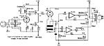
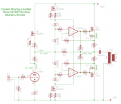
Funny you bring this up. I'm building a hybrid consisting of a SET stage with a true current boosting push-pull output stage.
The main ideas are:
Current is shared between the output stage and the SET stage by a ratio of 20:1 by virtue of the 20:1 ratio between R6 and R4,R5. This reflects the 250R OPT primary impedance back to the triode node at R1,R17 as 5K ohms.
The triode actually sees 10K plate load due to the 50/50 current sharing of the anti-triode Q5.
The output stage operates in class AB.
The idea is that the amp behaves just like a 20W SET into the real loudspeaker load, based on reflecting a constant % of the load current back to the triode plate while the output voltage nearly exactly follows the triode plate voltage.
Attachments
Last edited:
You realize the current of opamp steals from diode bias
depending wether its trying to push or pull upon the gate.
Effect is upon 2 diodes or the other, not the whole stack...
And especially if it overwhelms one of the gate zeners.
Was this an intended shutdown, or protection scheme?
depending wether its trying to push or pull upon the gate.
Effect is upon 2 diodes or the other, not the whole stack...
And especially if it overwhelms one of the gate zeners.
Was this an intended shutdown, or protection scheme?
You realize the current of opamp steals from diode bias
depending wether its trying to push or pull upon the gate.
Effect is upon 2 diodes or the other, not the whole stack...
And especially if it overwhelms one of the gate zeners.
Was this an intended shutdown, or protection scheme?
Yes, the tube stage powers the delta in opamp output current. Ideally the opamps should be bootstrap powered off the complementary MOSFET source terminals but this is easier to try out. 10mA should be more than enough to keep it all together.
Last edited:
Yes, the tube stage powers the delta in opamp output current. Ideally the opamps should be bootstrap powered off the complementary MOSFET source terminals but this is easier to try out. 10mA should be more than enough to keep it all together.
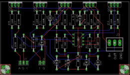
Actually not so hard to do it this way:
Attachments
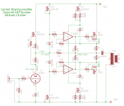
What happens to the voltage (series connection) between the Op Amps during a signal swing? Is it tracking the output?
Are you looking at the power supply connection that goes through the IC1B symbol? Both op amps are powered by the same +/- 12V offsets from the Q3 and Q4 sources.This tracks the output less the voltage drop across R4. R5
Funny you bring this up. I'm building a hybrid consisting of a SET stage with a true current boosting push-pull output stage.
The main ideas are:
Current is shared between the output stage and the SET stage by a ratio of 20:1 by virtue of the 20:1 ratio between R6 and R4,R5. This reflects the 250R OPT primary impedance back to the triode node at R1,R17 as 5K ohms.
The triode actually sees 10K plate load due to the 50/50 current sharing of the anti-triode Q5.
The output stage operates in class AB.
The idea is that the amp behaves just like a 20W SET into the real loudspeaker load, based on reflecting a constant % of the load current back to the triode plate while the output voltage nearly exactly follows the triode plate voltage.
Well, I was asking for a much more elementary reason. I'm building my first pp power amplifier - a transformer input differential circuit using video pentodes (cuz I got 'em) direct coupled to 2A3s . The drivers are loaded with Wavebourn's SVCS (The strange looking icons with ccs discs and the sine wave between) and the cathode circuit is like the cap coupled one that Shoog used on his EL84 amp.
I don't really understand them yet but I've always been interested in what you guys have been doing with the anti-triode and when I saw your schematic and realized I was assembling most of the parts anyway I thought it might be easy enough to get the op-amps and try it out somewhere along the way.
The idea of getting a single ended signature with one tube @ twice the power is appealing when thinking of tubes like the 45 or 10, but I haven't seen much in the way of subjective comments from people who have actually built and listened to them.
Attachments
Several points confirmed experimentally while half-year torturing of this particular design:
- with using a single CCS in output stage you are risking your 2A3s way too much. If one is accidentally pulled out (or heater is not up) - the second one goes to the spiritual world (of garbage bin) quick. Make the CCS' separate;
- hence, a differential stage better be the first stage, with a common CCS;
- actually, instead of the separate CCS in output stage 2 x Zener/resistor/cap work way better (cooler on temp and sonically sweeter);
- btw, 2 x 1400 uF is not any better than 2 x 14 uF, so just replace both with a single non-polar 20-50-100 uF - will be well sufficient.
UCMATH output stage
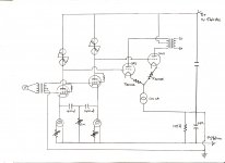
How about something like attached? I want to use some really good sounding transmitter tubes like the 316A, 3C24 and 801A as output tubes but obtainable power is very low and require expensive high impedance OT. Adding another conventional stage with regular output tubes like the EL34 with no feedback will most likely mess up 1W THD higher than 1%.
Trying to find another way I tried simulating several variations of George's idea with tube cascode to protect the mosfet. This is one of the more promising variant. Can use more affordable 2k5 transformer, does not require exotic parts nor huge heatsinks, ~0.09% THD at 1W at 20Vpp input, ~0.65% THD at 7W, 54Vpp input just before clipping. Mosfet dissipates ~4W and can easily tucked underside, a UCMATH, under cathode mosfet assisted tube hybrid.
However, JC Morrison warned that taking input to mosfet from cathode of a DHT will couple and amplify significant noise level directly to output transformer. I still consider myself a newbee for tube circuits, perhaps somebody could kindly share some pointer, experience, correction or insight before my build, especially regarding the noise issue. Thank you.
...
I built an amplifier about 2 years ago using a 45 tube with one Fairchild FQP1N50 (G connected to D) in the cathode and 2 more as the other side of the current mirror. They were wired up like a typical mosfet current mirror (I work with a bunch of CMOS IC designers). The amplifier worked great until you pushed it into clipping, at which point one or both of the mirror fets shorted. ...
How about something like attached? I want to use some really good sounding transmitter tubes like the 316A, 3C24 and 801A as output tubes but obtainable power is very low and require expensive high impedance OT. Adding another conventional stage with regular output tubes like the EL34 with no feedback will most likely mess up 1W THD higher than 1%.
Trying to find another way I tried simulating several variations of George's idea with tube cascode to protect the mosfet. This is one of the more promising variant. Can use more affordable 2k5 transformer, does not require exotic parts nor huge heatsinks, ~0.09% THD at 1W at 20Vpp input, ~0.65% THD at 7W, 54Vpp input just before clipping. Mosfet dissipates ~4W and can easily tucked underside, a UCMATH, under cathode mosfet assisted tube hybrid.
However, JC Morrison warned that taking input to mosfet from cathode of a DHT will couple and amplify significant noise level directly to output transformer. I still consider myself a newbee for tube circuits, perhaps somebody could kindly share some pointer, experience, correction or insight before my build, especially regarding the noise issue. Thank you.
Attachments
Hi,
I would say that the basic concept of a parallel SET current multiplier using a MSOFET-tube cascode is definitely workable and should yield great results. And, as you say, it solves the heatsink issue in a nice way.
As a design, I would suggest that there is some more work needed.
The biggest issue I see is that the attached circuit is highly depending on the transfer characteristic of the MOSFET in its very non-linear region, at low drain current.
Building the exact circuit would probably not result in either a stable operating point, or dependable current multiplication ratio.
I would recommend looking at a servo arrangement as described in some of the earlier posts in this thread, with a corner frequency of about 10 Hz to start with. This could be a place to start experimentation while you work out some of the circuit optimizations and simplifications.
BR
Michael
PS as for the noise question, I don't see any such issue in the designs I have built using MOSFET based cathode current mirrors.
Last edited:
Very encouraging, thank you Michael. Yes, a kind of servo is being worked on, something with an opto like Pass's M2.. . . . as for the noise question, I don't see any such issue in the designs I have built using MOSFET based cathode current mirrors.
Hi Michael, using BJT instead of mosfets would allow you to hang a NPN - PNP buffer off of the tube directly. then bias them with 3 or 4 diodes and 100 ohm emitter resistors.
4 diodes yeilds about 7ma bias. the 10ma tube bias provides plenty of base drive along with no need for the op amps or a floating power supply.
4 diodes yeilds about 7ma bias. the 10ma tube bias provides plenty of base drive along with no need for the op amps or a floating power supply.
- Status
- This old topic is closed. If you want to reopen this topic, contact a moderator using the "Report Post" button.
- Home
- Amplifiers
- Tubes / Valves
- Another kind of hybrid