I've refined a better explanation of my last drawing:
(for the benefit of lurkers having diffculty following)
The Darlington communicates the music signal to the
Triode by AC Voltage. The AC Voltage at either end of
the tail cap follows the input of lowest impedance.
The Darlington would pass nearly unlimited current
if it only that current had somewhere else to go...
The Triode communicates back to the Darlington by a
much more limited AC current. The limited AC current
through our cap is now the music of a true SE Triode.
The Darlington simply passes this current and begs
for more...
The Darlington acts as a Cascode to loop this current
back up to the other end of the load, completing a true
Push-Pull circuit for the output transformer.
Music currents can't get past the impedance of either
tail source, only DC bias is permitted to flow there.
Voltage (and original signal) tracks the Darlington.
(or whichever input is of the lowest impedance).
Current is a Single Ended function of the Triode.
(or whichever input is of the higher impedance).
The input could be made at either Darlington or Triode
or differentially to both, the result is the same. But our
Darlington may be the preferred input, as it grants the
option to drive our Triode into A2 without need for any
extra parts. Simply ground the grid of the Triode.
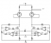
Phase splitter
"Regarding MJK's latest OpFET arrangement..."
Doh!
Yeah, it's a perpetual motion machine actually... Both latest cathode balance schemes come to think of it are not AC coupled as pictured.
I'll have to think about this some more, as it seems to want to
degenerate to this... There was a cathode current version of
the differential gyrator somewhere. Oh well...
Michael
Attachments
Cathode Voltage Regulator
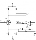
OK, I'm going to have to come out with another thing I've been working on to to show the whole circuit for the AC/DC balanced current source.
This is basically a cathode voltage regulator, in a cascade connection driven by current regulators.
The voltage regulator control inputs are AC coupled but allowed to have a DC offset to accommodate the different conductance in the tubes.
This circuit does what the brute-force coupling cap in Ken's earlier post does but with a small cap. The whole thing could go on a little PCB.
But... I have something a little more sophisticated in mind...for later
Michael
Attachments
Rediculous Bridge Cappage
I've seriously miscalculated the cap in the tail bridge.
Assuming it carried the same current as Parafeed, true.
But forgot the voltage drop is now almost nothing.
R=E/I, and the cap has to be absurdly large to couple
a Darlington's emitter to the cathode of a 101x Triode
Multipler. Impedance is in the single digits... Almost
necessitates a bypass with some nasty electrolytic.
I am abandoning this iteration as impractical...
I am not sure I understand Michaels new variant,
nor why its better than his first OpFet mirror with
fewer parts? But he's correct to see my cap as an
isssue of concern that has to be solved.
Also this schematic has way too much voltage gain
(assuming a much bigger cap than 4.7uf as drawn)
I forgot I wanted to design for a 1V P-P input...
There are a lot of things about this schemtic I now
think were kinda silly in retrospect.
Attachments
"I am not sure I understand Michaels new variant,
nor why its better than his first OpFet mirror with
fewer parts? But he's correct to see my cap as an
isssue of concern that has to be solved."
It's precisely the cap that's the issue. In a line stage, or limiter, filter, etc. I'd be inclined to use the cap-coupled CCS because a reasonable cap does the job. But for a power amp, I wanted to AC couple the control signal rather than the cathodes themselves.
I don't think the Cathode Voltage Regulator does the same thing as the current mirror. The CVR solves the problem of AC coupling and cathode coupling that the earlier broken circuits lacked. For a differential current mirror with balanced DC current, post #183 I think will work and won't need a humongous cap.
Plus there's another variant of this circuit which address the distortion current issue with diffamps where f2 gets converted to f3. I'm still tweaking that design and will show it soon.
For a phase splitter the current mirror circuit in post #182 will do the job while retaining SE driver harmonic structure. It would be used to drive a conventional or balanced-boost P-P output stage for example. I think it may have trouble with a lot of grid current though...
Cheers,
Michael
"R=E/I, and the cap has to be absurdly large to couple
a Darlington's emitter to the cathode of a 101x Triode
Multipler. Impedance is in the single digits... Almost
necessitates a bypass with some nasty electrolytic.
I am abandoning this iteration as impractical..."
So you're using the current sharing circuit to drive the triode darlington implicitly. Will my latest (post 183) circuit work for you?
Ken,
Ummm.. 100's of Watts from a 12AX7? Gonna be hard to explain that one to your visitors. And too much gain. Maybe you should use one of those dual vertical TV amp tubes. Less gain, lower Rp, costs less, and might even look like it could put out some power (try to find a big one).
The 12AX7 is practically a no feedback pentode anyway at 100 Mu.
On the cap., yeah, probably gonna need a big honker electrolytic. Well, the bigger it is, the less voltage that drops across it, so the less sonic effect it can have. So go all the way: 1 Farad at 10V maybe? Couple in parallel?
Don
FakeOde
Neither of these FakeOde's work in A2 yet.
Non-Inverting one needs to be driven positive.....
Non-inverting FakeOde can't utilise cathode feedback...
Nor can it be used LTP or as a cathode follower...
Least not in any conventional way.
The Mach1 should behave more like a normal triode.
If you load the plate with constant current, you won't
see a better FakeOde. If current through the diode is
held too constant, you only see transistors in action.....
You need a resistive load to see significant influence
by the Diode's plate curve....
The cascode hides a linear 10x plate voltage per grid
volt. Mimicking the near parallel curves of a good triode.
Or at least thats how I hope its supposed to work...
The solid diodes in the Mach1 are only to move the A2
point to up to 0V. With improper biasing, they could just
as easily be eliminated, and permit the individual abuse
of twin vacuum diodes that share a true common cathode.
Attachments
Still trying to find a way to lean diode curves to the right.
The spacing between triode curves near cutoff should be
about 4 volts per grid line, vs 5 volts near full saturation....
Or some other two voltages about the same 4/5 ratio...
I am not so sure it make a huge difference along a purely
resistive load line, but probably necessary for realism with
other flavors of plate loading...
"Still trying to find a way to lean diode curves to the right."
The usual explanation for the tilt of the curves is that the lower Mu portions of the tube are slower to turn off. So if you combine a low Mu and high Mu tube or model, you should get something similar.
A little OT, but since we are trying to model high current tubes using a hybrid approach here, 8 years ago some researchers figured out how to make no filament tubes that can handle high currents:
http://www.diyaudio.com/forums/showthread.php?postid=12238#post12238
Mainly display panel research that is interested in it. Too bad no one has come out with a simple triode product. Could be in a glass bulb for low power tubes, and in a TO-264 package for high power. Laser perforated sheet metal grid (graphene overlaid grid support maybe later), a ceramic layered package using silver solder bonding (pretty much available off the shelf), three leads, 300 Watt, 250V, 15 A.
I have modern vacuum equipment in storage to make a prototype (the cathode can be made with just electroplating technology, no expensive semiconductor fab equipment required), but would need some serious venture capital to get beyond that point. Not likely to be much of a market initially either, until some design-ins occur. One concern is how well the vacuum will hold up in a small package. But plasma display panels have the same problem.
Don
Lean To The Right
Would you suggest paralleling a 20Mu FakeOde with a 25Mu?
Do the gradual (but unequal) pinchoffs of this pair mimic the
lean to the right of a normal Triode (in A1)?
I could probably have done two resistors in series (1 Meg +
250K) , and saved one redundant transistor below the true
cathodes of the diodes. Perhaps this ratio of 4/5 is not the
proper blocking ratio of resistors?
I get 4.5 mu average at high current? but only 2mu at low...
4.5/2~mu/mu is not the lean to the right what I wanted...
I got my maths all mixed up now somehow... May not add
together that way either.
Attachments
Audio Express van Doorn Hybrid "OTL"
I just saw Broskies article about the latest Audio Express issue's Hybrid OTL by van Doorn. Would seem to be of some interest for Hybrid schemers like us.
http://www.tubecad.com/2008/04/blog0140.htm
Broskie pretty much dismisses the design as futile. The design does have a serious flaw in my opinion (and Broskie points out the same), since it "emulates" a pentode instead of a triode. (uses the same current sensing approach Ken and Michael have used but in the plate circuit instead) But, I don't want to be too negative here, its still good to see some attempts at new ideas being made. One has to expect some criticism on new designs till they are ironed out.
If it used a triode for the tube emulation, then the triode's actual % power output contribution to the load is really immaterial. (Broskie makes a big deal about the tube doing nothing power wise.) The point would be that the triode sets the voltage output and the power Op. amp. would be putting the load current out as a modulated current source.
The Tubecad alternative hybrid offered subsequently is pretty close to conventional hybrids, with a tube input stage and SS output, with the exception of the Aikido like triode current source loading the CF input. I think his assertion that the triode CCS is more linear than an ideal CCS is an artifact of the tube models used by SPICE though.
For simple 3/2 power law triode models, and perfectly matched simulator tubes, the combo does give linear results. But real tubes won't act that way since they are voltage sensitive as well. (the top and bottom triodes track current wise, but not voltage wise. Mu variation with plate voltage is not modeled by simple simulator models. Aikido simulations do the same thing, linear with simulator models, not so linear with real tubes. Low power levels are what rescue it.)
Don
Dual Diode FakeOde
Here I parallel a 6 Mu FakeOde with a 4 Mu FakeOde.
This should give an average Mu of 5, dimishing to 4
as the higher Mu FakeOde cuts off...
I am not sure why 4 by itself it does not average to
a Mu of only 2 with the higher Mu curve in cutoff???
Yet even with this blatant "mistake" the curves look
about what I was shooting for... go figure...
Cutoff seems a bit angular with ^1.5 power function.
Seems smoother as transfer function approaches ^2.
Attachments
4 way average
Four parallel FakeOdes with Mu's of 6, 5, 4, and 3...
I scrunched the height by factor of two for sake of
familiarity of appearance, more like what one sees
in spec sheet.
Not yet sure how important all power rectifiers need
to match? For fudging leaning curves like a triode.
Imagine big 4 directly heated diodes (two tubes).
Plus the Mu voltage hiding of 4 IGBTs in cascode.
This would be one serious Bogey...
The equation for the -1V grid curve as calculated...
(((x-06)*(x>06))^1.5+((x-05)*(x>05))^1.5+((x-04)*(x>04))^1.5+((x-03)*(x>03))^1.5)/4
The equation for the -2V grid curve as calculated...
(((x-12)*(x>12))^1.5+((x-10)*(x>10))^1.5+((x-08)*(x>08))^1.5+((x-06)*(x>06))^1.5)/4
Etc...
Assuming such rectifiers actually obey y=x^1.5.
Reality might be slightly different, but thats OK.
Using actual vacuum diodes for the reality check.
Attachments
The graph gives supporting argument for Smoking's hypothesis.
That real triodes consist of multiple pathways of different Mu.
Those of lowest Mu (remotest) cut off last. Thus the lean...
To his hypothesis I will add:
To make a truly linear triode (for a resistive load) you would
need to have completely consistant Mu over the entire device.
But such consistancy is completely irrelevant to linearity as
long as the load is a constant current.
------------------------------------------------------------------------------
Sadly, I can fake a "perfect triode" from a single diode much
easier than faking an imperfect triode that behaves like reality.
6,5,4,3 fake again...
Truncate the plate curves like they do in the spec sheets.
It really starts to look almost convincing.
Yet there is little chance of a simple way to fake A2
triode curves here... For that I would need to current
multiply a real reference triode... But it needn't be
anything high powered or expensive.
I just like the idea of direct heated diode for a reference.
Thinking perhaps I can stuff something like that into a
300B socket and not have to muck with faking the 5V
filament? But even that has issues, we already see that
two diodes is not enough for smooth lean to the right.
And most of the power rectifiers pull abut 2 Amps for
filament, 300B only pulls 1.2Amp. Needs more thought.
Attachments
For those not following what the last set of fake curves was about...
Here's one possible implementation. Note this gate need not be
truly negative with regard to the cathode, only negative to VBias.
Which could be a string of LEDs , a Zenier, or whatever...
Other bias arrangements are possible.
Who wants to take a crack at a P-Channel variant?
Here's one possible implementation. Note this gate need not be
truly negative with regard to the cathode, only negative to VBias.
Which could be a string of LEDs , a Zenier, or whatever...
Other bias arrangements are possible.
Who wants to take a crack at a P-Channel variant?
Attachments
Ken:
6JU8, its got four diodes in it (but some bridge prewiring), cheap as fishing line bobbers. (6AL5 has two, 6GQ7 has three) Your Fakeode looks promising. Maybe could use a current mirror with gain to increase the final gm with the small diodes. P tubes next?
(Oh, by the way, the best triodes are generally considered to be the ones with the least tilt in the curves, before you get too carried away.....)
Don
smoking-amp said:P tubes next?
I expect some of the "lean" in the spec sheet may be the
averaging over a sample set. Individual triodes may not
lean quite so severely as the book, yet the Average does...
I bet remote cutoff pentode strapped as a triode leans
far more severe than a sharp cutoff of similar construction.
And the Mu averaging need not be spread so wide as I
have presented in my graph.... Mu is completely arbitrary
in a fakeode, set however you wish.
Not sure the N FakeOde can pull down hard enough to
starve off the entirety of volts to the plate(s), and that
may yet require a negative supply rail.
The P version can pull down as hard as the CCS, and I
may "flip" the N version again as another way to get full
rail swing for the Mu starvation.
Attachments
- Status
- This old topic is closed. If you want to reopen this topic, contact a moderator using the "Report Post" button.
- Home
- Amplifiers
- Tubes / Valves
- Another kind of hybrid