C1 is gonna need to be pretty large I think.
Its coupling almost pure current from the
cathode to emitter. At full swing, a high
fraction of what either current source has
set for quiescent bias.
Both ^ sources are possibly mirrors of one
shared reference off to the side somewhere...
Its coupling almost pure current from the
cathode to emitter. At full swing, a high
fraction of what either current source has
set for quiescent bias.
Both ^ sources are possibly mirrors of one
shared reference off to the side somewhere...
The cap. needs to be a low impedance (at 20 Hz) compared to 1/Gm of the tube, and able to handle AC (non-polar).
Or else just use an inductor for the tail (no cap) and adjust the Darlington or Mosfet side gate bias to equalize DC currents at idle.
I think that will still give a sort of balance against distortion current buildup. The increased inductor current buildup after loud passages will then spill into the SS side during soft passages until dissipated off. Might cause some sonic effect though.
Maybe should use a resistor (and series cap?) in parallel with the inductor, likely about equal to the Western Electric 3rd harmonic equalizer value.
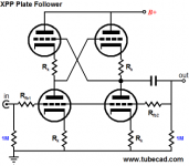
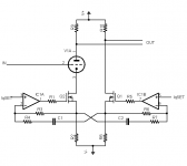
Hmmm... Driven from the other end, its still an Anti-Triode...
The Emitter follower simply impresses the input signal at
the Cathode instead of the Grid...
Since we are now driving with an emitter follower, A2
mode should be extremely easy. Merely ground the grid!
But I don't want A2 or base currents leaking in our out
to mess with the experiment.
Slight re-arrangement assures all currents both branches
are properly accounted for. Nothing gets in or out except
through the current sources.
Mosfets might not be the ideal input follower. Junction
FETs might have been better, but need a cascode or
something to handle the drain voltage. Perhaps small
triodes following in A1, yet driving A2.... Yeah thats it!
Really, any of these drawings, just assume a cascode
for any transistors. I didn't bother to draw a top device....
Probably (for clarity) shouldn't have bothered drawing
the gate stoppers either. I neglected a Grid stopper.
Attachments
Hi Ken,
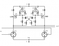
Driven from either side, it's the same... Very interesting topology. Of course Op-Fet cascodes will work WELL in this application.
The AC-coupled CCS pair looks like a good solution for balancing any diffamp! I may have a triode-triode "plain vanilla" use for that circuit.
"Both ^ sources are possibly mirrors of one
shared reference off to the side somewhere..."
Strange, I've been working on a class of circuits you might call a sort of differential gyrator, trying to work out a DC coupled version of the thing above. One is a constant common-mode voltage regulator and another is a balanced-current regulator.
The A.D. Blumlein "garter" cross-coupled bias circuit is sort of an inspiration for the balanced-current thing.
The common-mode voltage regulator came about looking for a replacement for a common-mode choke with "zero" DCR for a differential anode load to use on the plates of a beam-deflection tube.
Cheers!
Michael
I've seen a circuit used in a SS amplifier that acted like a two way complementary current mirror. Two high Z outs, as long as the currents summed to a constant. It was used as the termination for a differential VAS stage, which must have driven a bridged output. I'm thinking it may have been a design by J.L. Hood. But so far I haven't found it in any of his books, so probably an Electronics World/Wireless World article.
Don
Don
Ironic that the more capable device becomes the slave.
If the reverse were true, our reference triode might act
Anti-Transistorish. The lesser conductive, lesser gainful,
lesser B+ screening device sets the proper misbehavior
for both ends...
And I'm fairly sure that driven from either end (or both)
that it's SEPP behavior mimics a pair of identical parallel
triodes in SE.
If the reference tube is enlarged with a plate mirror,
we must be careful the solid side never becomes the
weaker device.
Whichever device is the stonger, acts as a flavorless
voltage follower. Merely a cascode above the current
limit, the sum of a bias and the tail coupling current.
"Hmmm... Driven from the other end, its still an Anti-Triode...
The Emitter follower simply impresses the input signal at
the Cathode instead of the Grid..."
Would seem an easy mod for an existing P-P tube amp. Just pull one tube out, put in a Mosfet/Darlington and CCS (or dual CCS/cap) tail. Maybe scale the Mosfet side drive signal down until the tail voltage variation reaches a minimum. Voila, P-P SET.
I gather we are now contemplating a current mirror or multiplying mirror on the tube plate side and a big honker Mosfet or Darlington on the other side. Unlimited SET power output.
How about building each stage of the amplifier this way. P-P sorta-symmetrical design, SET sound. (ie, drive both tube and SS sides of each diffl. stage. Maybe this is what Michael is thinking.) Could use some SS emulation of a center tapped inductor load for the intermediate stages. A P-channel diffl stage, resistive tail to B+, with common mode servo'd equal gate voltages to keep "plate" voltages in the center of the operating range. Seems like we don't really need voltage parity between the tube and SS sides of each pair up through the chain until the last OT, so some assymetry of plate loading currents might be considered.
Seeing as Gm scales with current (for Mosfets), we better check that our SS side really has more Gm than the tube side. Some tubes come close to the 1 Sieman per Ampere spec for Mosfets, just are rated at lower currents than the Mosfet data sheet normally does. For bipolars, I guess we are safe.
OTA's, linear Mosfets. Could be interesting. More options.
By the way, I think a JFET can be run with its drain and source flipped. This might give a triode effect with some devices since the gm is likely optimised for the usual way only. I don't think they have the substrate diode problem generally.
Don
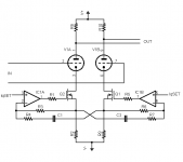
Differential Gyrator
Ken: "Maybe this is what Michael is thinking.) Could use some SS emulation of a center tapped inductor load "
Here it is, but it's pretty ugly!
It's supposed to maintain stiff common mode response (like a perfect zero DCR common mode choke) and allow equal complementary voltage swing.
In it's current form, it regulates voltage drop from B+ by the CC drop thru R3 and R8. Could use a cascode of course but this might be good enough.
Regulating off gnd would be an improvement...
Michael
Attachments
Re: Woody
Well, the bottom right output tube is acting as a voltage gain tube, so if you replace that one, you will be into depl. Fet sound. (Which could be fine, but... ya know, breaks the rules, go to jail...)
Maybe better to replace the top two tubes with depl. Fets or Mosfets, since they are just acting as followers for the tube gain stages below, and higher gm is better for followers.
For more current output than the bottom output tube can provide, you could put a Mosfet CCS pulldown on the output. That way the top Mosfet can provide heavier current output. (but the bottom tube won't be doing much anymore)
Or..., see attached diagram for a replacement of the bottom output tube. (but this scheme is simpler if it just uses N and P channel Mosfet followers in totem pole itself, then you can skip the original top output follower altogether)
(and the feedback to the pentode screen eliminates most of the enclosed Mosfet follower sonics as well)
Don
Attachments
Re: Woody
Here is what I meant about just doing the whole output using screen feedback and totem pole Mosfets. This would just replace the two right side tubes in the original diagram. Could still put a bootstrapped Mosfet follower on the top left side of the original for the input triode's active (constant current) load.
The totem pole Mosfet outputs could drive a speaker directly if they are beefy enough (or try Darlington config.). Needs some level translation (B- supply for the tube cathode and a DC servo) to get centered at 0 V out for the speaker, or just put thru a big cap.
Don
Attachments
OOPs Correction
My CT inductor scheme in post 176 above is a bit tooooo optimistic. It lacks any differential signal to the Mosfet gates, so it cannot vary its differential current. I think that could be remedied by placing some resistance between the Mosfet gates and separating the drain feedback resistors R2 and R3 to those gates. Really becomes more of a differential resistor then, with low common mode Z still, hopefully. (modified diagram attached)
Could keep the differential resistance fairly high I guess.
But the whole premise of lightly loading the tube(s) needs re-evaluating here. Assuming this is using the cathode mirror scheme and a SS device on one side (in place of V2). A high Z load on the tube (V1) means its plate current stays constant, and so the current mirror and SS device just act like a current source on the other side. Not so useful.
Some re-thinking required on this scheme yet for intermediate gain stages.
Don
Attachments
Regarding MJK's latest OpFET arrangement...
Seems that the current is forced to quiescent rather than
opposite of whats happening under the other cathode.
If the voltgage at r8 (the undriven side) is steady at
some quiescent bias. Near infinate gain of IC1A + Fet
will hold the driven side at its own quiescent current.
Regardless of the input.... Which then causes nothing
of interest to happen again back on the undriven side.
Seems not to matter if the caps are big or small, the
cycle of nothing fun appears to be completely stable.
Maybe I am reading this wrong...
- Status
- This old topic is closed. If you want to reopen this topic, contact a moderator using the "Report Post" button.
- Home
- Amplifiers
- Tubes / Valves
- Another kind of hybrid