we have boards
Since you guys seem to be having some trouble pulling this together I will mention once more that we have been using this CCS design for many years, and we have boards.
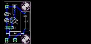
We have a couple of flavors. The older design is one we have for sale on the website as a kit with transistors and LEDs and fairly extensive documentation. It only needs the addition of the resistor values needed for setting the specific bias and plate current for a given application. The kit contains two cascode constant current sources, one per board. The board is perfectly functional and easy to populate, but I won't say that it's the most compact or logical layout. Since you guys are very DIY I could probably be talked into selling boards only for a reasonable price if you can pull together a group buy and plan to do your own parts acquisition and tech support within the community. Here's a pic of a couple of them.
A newer design has space for two of the same design CCSs as the original board, plus the SS components of a pair of hybrid tube/SS shunt regulators. This is what we currently use in most of our products. It has a more dense layout and this one doesn't have stand alone documentation at this time, but it does have a component screen. If you guys are adventurous enough to tackle this board without a lot of tech support I could probably make it available in quantity for a group buy as well. Here's an image of three of the boards in a couple of different configurations. These boards can also be split in half to make individual CCS/shunt regs.
If this is of interest, feel free to volunteer someone from your community to be the facilitator and have them contact me, and I'll be happy see what I can do to make a good deal for the group.
Since you guys seem to be having some trouble pulling this together I will mention once more that we have been using this CCS design for many years, and we have boards.
We have a couple of flavors. The older design is one we have for sale on the website as a kit with transistors and LEDs and fairly extensive documentation. It only needs the addition of the resistor values needed for setting the specific bias and plate current for a given application. The kit contains two cascode constant current sources, one per board. The board is perfectly functional and easy to populate, but I won't say that it's the most compact or logical layout. Since you guys are very DIY I could probably be talked into selling boards only for a reasonable price if you can pull together a group buy and plan to do your own parts acquisition and tech support within the community. Here's a pic of a couple of them.
An externally hosted image should be here but it was not working when we last tested it.
A newer design has space for two of the same design CCSs as the original board, plus the SS components of a pair of hybrid tube/SS shunt regulators. This is what we currently use in most of our products. It has a more dense layout and this one doesn't have stand alone documentation at this time, but it does have a component screen. If you guys are adventurous enough to tackle this board without a lot of tech support I could probably make it available in quantity for a group buy as well. Here's an image of three of the boards in a couple of different configurations. These boards can also be split in half to make individual CCS/shunt regs.
An externally hosted image should be here but it was not working when we last tested it.
If this is of interest, feel free to volunteer someone from your community to be the facilitator and have them contact me, and I'll be happy see what I can do to make a good deal for the group.
Tube Prototype PCB with CCS Pads 9-pin Mini
http://cgi.ebay.ca/Tube-Prototype-P...ryZ50598QQssPageNameZWDVWQQrdZ1QQcmdZViewItem
http://cgi.ebay.ca/Tube-Prototype-P...ryZ50598QQssPageNameZWDVWQQrdZ1QQcmdZViewItem
An externally hosted image should be here but it was not working when we last tested it.
Okay. I could be convinced to do this project. But, my experience with PCB manufacture is that the multiple boards on one sheet with v-scoring will drive up the price considerably. Moreover, I think lots of people would only want one board or another.
So, if I were to do it, I'd offer 3 different boards and run it like other group buys where people need to agree to, and pay for, boards in advance. I would think $2 to $3 per board plus some shipping would be reasonable. There would also be no reason not to include boards for single and dual IXYS chips, I suppose.
The only rub is that as a group buy it would need to be at the buyer's risk -- that is, I would not take back boards that had a manufacturing error, or that had a design error (presumably lots of eyes would look at them before they were ordered) and boards lost in shipping would not be my responsibility (really, the only boards that ever seem to get lost in shipping are those going to Italy.)
So, if people are interested, let me know and I'll post up the designs and start a group buy thread ...
I am..So, if people are interested, let me know and I'll post up the designs and start a group buy thread ...
That was what I worried about when managing a GB,that boards would get lost on the way,fortunate it all went well..
")
So, if people are interested, let me know and I'll post up the designs and start a group buy thread ...
I'm interested.
This thread looks like it is about to get out of control. I recommend that anybody discussing Doc B. or dsavitsk boards start a new thread, and that the original boards that are now being handled by myself, planet10 and beamnet remain in this thread. Don't take this is as mean spirited, as I would be very interested in participating in GB's for those boards as well
I think that's a good idea (the new thread, that is). Also, I'd rather not have to run a group buy, it just seems like there are lots of folks looking for boards and that it is not going anywhere.
As for the Bottlehead designs, with all due respect, based on past dealings with them, I have my doubts about getting these down into the $2 to $3 range. I also have my doubts about the designs being made public and being discussed. If Doc B wants to post some schematics, enter into a discussion, and give a little back to the community, then I am all in favor of going that route.
Also, what might end up being easier for everyone, is to put a few designs up complete with Gerbers. Then, you could pick your favorite CCS boards and send them to Olimex who will panelize them onto a single sided PCB that will hold 10 to 12 small boards for EUR 24 + shipping. Presumably, few people need a dozen, so a small side market or 2 to 3 person group buys could be arranged. The transaction costs per board are a little higher, but it is a lot easier for me to not have to manage hundreds of boards, and people might be more likely to get what they want.
http://img.photobucket.com/albums/v323/cetoole/millett/sleep.jpg
dsavitsk said:So, it looks like 24mm X 40mm is pretty easy to do, which would mean 16 boards from Olimex for ~30 shipped.
I suggest that you orient the pads for the power transistor so that it can be heatsinked. You can discuss this in the new thread
Is it just me or has this thread now gone backwards?
There are 5 different designs for people to look at. These are just first revisions, and they can be altered if anyone has suggestions on how to do that. They are the three basic designs already done, with the addition of a HV PNP design that uses a different transistor as well as a design that uses either the IXYS 10M45 or the DN2540N5 (you can use two, or you can cleverly jumper a connection to use one.) The HV PNP boards also have a spot for a cap to quell any oscillations that can crop up -- it is optional.
Once a consensus is reached I am happy to either order a round of boards, or to post Gerber files for these so that people can order their own boards from Olimex as explained above, or both. If I am to do the ordering, boards will probably be $2.50 each + shipping with a discount for orders over 10 or so. I will need to get orders for a minimum of 50 for any particular type to make the order worth doing.
Alternatively, if there are orders for about 70 or so of a mix, I might be able to swing that, too. And, boards would be RoHS compliant, and can be 2oz copper (which would probably add $0.10 per board.)
And finally, turn around time from the board house is typically about 7 to 10 days, so it is certainly possible to get these to people by X-Mas if things move quickly.
HV PNP A
HV PNP B
HN NPN
LV NPN
IXYS
Once a consensus is reached I am happy to either order a round of boards, or to post Gerber files for these so that people can order their own boards from Olimex as explained above, or both. If I am to do the ordering, boards will probably be $2.50 each + shipping with a discount for orders over 10 or so. I will need to get orders for a minimum of 50 for any particular type to make the order worth doing.
Alternatively, if there are orders for about 70 or so of a mix, I might be able to swing that, too. And, boards would be RoHS compliant, and can be 2oz copper (which would probably add $0.10 per board.)
And finally, turn around time from the board house is typically about 7 to 10 days, so it is certainly possible to get these to people by X-Mas if things move quickly.
HV PNP A
An externally hosted image should be here but it was not working when we last tested it.
An externally hosted image should be here but it was not working when we last tested it.
HV PNP B
An externally hosted image should be here but it was not working when we last tested it.
An externally hosted image should be here but it was not working when we last tested it.
HN NPN
An externally hosted image should be here but it was not working when we last tested it.
An externally hosted image should be here but it was not working when we last tested it.
LV NPN
An externally hosted image should be here but it was not working when we last tested it.
An externally hosted image should be here but it was not working when we last tested it.
IXYS
An externally hosted image should be here but it was not working when we last tested it.
An externally hosted image should be here but it was not working when we last tested it.
Error, error.
What is that fixed resistor doing in parallel with the current programming resistor in the first two drawings? It should be in series (like in the second two). Also, 2N2907A doesn't have a particularly high current gain - you want as much as possible in that position. BC557C is the best (hfe > 400).
What is that fixed resistor doing in parallel with the current programming resistor in the first two drawings? It should be in series (like in the second two). Also, 2N2907A doesn't have a particularly high current gain - you want as much as possible in that position. BC557C is the best (hfe > 400).
What is that fixed resistor doing in parallel with the current programming resistor in the first two drawings?
Wouldn't it be a good idea, generally speaking, to calculate the needed resistance to set the current under ideal conditions, then take a fixed resistor of a slightly higher value and parallel it with an adjustable potentiometer with higher ohmic value to set proper current? This way one allows for the tolerances, and the potentiometer is not subject to all of the current flowing through the CCS!?
And to Dsavitsk, about the IXYS board...what is the maximum current one can set through the cascoded IXYS chips?
Many thanks, Erik
ErikdeBest said:Wouldn't it be a good idea, generally speaking, to calculate the needed resistance to set the current under ideal conditions, then take a fixed resistor of a slightly higher value and parallel it with an adjustable potentiometer with higher ohmic value to set proper current?
Not quite. Think about what would happen if the adjustable resistor was set to zero resistance. It's best to have a series resistor to prevent the current programming resistor accidentally being set to zero. Write yourself a spreadsheet to investigate the effect of a series resistor and a variable resistor and you'll see what I mean.
Hi EC8010
Thanks for explaining, and I understand it. Actually I have already applied it! I set up a LV CCS with about 90% of the desired current going through a low value setting resistor...the other 10% went through a higher valued potentiometer in series with a resistor of the same value as the potentiometer.
Erik
EC8010 said:What is that fixed resistor doing in parallel with the current programming resistor in the first two drawings?
ErikdeBest said:Wouldn't it be a good idea, generally speaking, to calculate the needed resistance to set the current under ideal conditions, then take a fixed resistor of a slightly higher value and parallel it with an adjustable potentiometer with higher ohmic value to set proper current? This way one allows for the tolerances, and the potentiometer is not subject to all of the current flowing through the CCS!?
That was the idea. It can certainly be changed if it is a bad idea, but it seems like a reasonable way to go. I also figured people could use the trimmer to set them up, then just replace it with a fixed resistor, and the extra pads might be useful for this.
EC8010 said:Also, 2N2907A doesn't have a particularly high current gain - you want as much as possible in that position. BC557C is the best (hfe > 400).
Okay, we'll call the BC557C the preferred version and plan to concentrate on it.
ErikdeBest said:And to Dsavitsk, about the IXYS board...what is the maximum current one can set through the cascoded IXYS chips?
I don't really know, but the datasheet says they can dissipate 40W with appropriate heatsinking.
Gluca said:Why don't you add a phoenix connector for IN/LZ1/LD1?
I'll see what I can do
EC8010 said:
Not quite. Think about what would happen if the adjustable resistor was set to zero resistance. It's best to have a series resistor to prevent the current programming resistor accidentally being set to zero. Write yourself a spreadsheet to investigate the effect of a series resistor and a variable resistor and you'll see what I mean.
That is the inherent danger, so if there is room, I'll try to add a series resistor as well.
- Status
- This old topic is closed. If you want to reopen this topic, contact a moderator using the "Report Post" button.
- Home
- Amplifiers
- Tubes / Valves
- Another CCS for tubes/valves: PCBs