Thats not teh issue ZM and you know it. The issue is that if ya load a 20 k demanding poweramp with a regular anodefollower you might win or you might loose. And you dont know it on forehand. That is because anode follower preamps tend to change their bias point to whatever load they take.
Constructing a decent preamp is harder then this, unless you want to spend the rest of your days in a callcenter. Im sure you know what I mean. I have C3G on my breadboard.
Kisses
Staffan
Constructing a decent preamp is harder then this, unless you want to spend the rest of your days in a callcenter. Im sure you know what I mean. I have C3G on my breadboard.
Kisses
Staffan
...... The issue is that if ya load a 20 k demanding poweramp with a regular anodefollower you might win or you might loose. .......
not disputing that
")
Hey Salas,
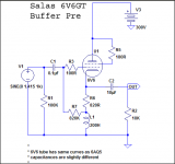
Why make such a unecessary overpopulated design with yet another sound-degrading cap at the input.
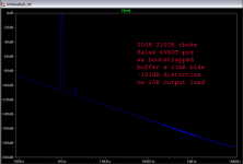
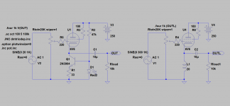
As Ug is high a CCS is enough with grid related to ground. If more swing is need, as the CCS-version clips at the negative side at maybe 10Vrms, a choke with suitable DCR should be used. If no standard choke is available, I guess Dave Slagle will easily build one. If one have a choke with lower DCR than needed only a small, added series-resistor is needed.
In my example Ia is 30mA and choke DCR 500ohm. 20H gives -3dB at 5Hz. I would go for 50H.
Why make such a unecessary overpopulated design with yet another sound-degrading cap at the input.
As Ug is high a CCS is enough with grid related to ground. If more swing is need, as the CCS-version clips at the negative side at maybe 10Vrms, a choke with suitable DCR should be used. If no standard choke is available, I guess Dave Slagle will easily build one. If one have a choke with lower DCR than needed only a small, added series-resistor is needed.
In my example Ia is 30mA and choke DCR 500ohm. 20H gives -3dB at 5Hz. I would go for 50H.
Attachments
Last edited:
Indeed! What happens if you put a rock steady 250 on g2?
Does 2dB worse THD.
Hey Salas,
Why make such a unecessary overpopulated design with yet another sound-degrading cap at the input.
As Ug is high a CCS is enough with grid related to ground. If more swing is need, as the CCS-version clips at the negative side at maybe 10Vrms, a choke with suitable DCR should be used. If no standard choke is available, I guess Dave Slagle will easily build one. If one have a choke with lower DCR than needed only a small, added series-resistor is needed.
In my example Ia is 30mA and choke DCR 500ohm. 20H gives -3dB at 5Hz. I would go for 50H.
*I need pot.inc
I like the non BJT aided bootstrap subjectively, with Teflon cap I could not feel it bit more opaque.
Hey Salas,
* A Collection of Potentiometers
* ==============================
* Helmut Sennewald, 12/23/2003 V1.1
*
* Models:
* potentiometer old style LTSPICE potentiometer
* pot_lin k*x
* pot_pow x^k
* pot_plog exp(k*(1-x))
* pot_nlog exp(kx)
* pot_tab table(x)
* pot_piher_plog piecewise linear, datasheet
* pot_radiohm_plog piecewise linear, measured
*
*
* 1 ____ 1.0=wiper
* |
* | | 3
* | |<---- wiper 0..1
* | |
* Rtap | | Tap
* | |
* 2 ____| 0.0=wiper
*
*
* RTOT = total resistance
* WIPER = ratio of travel of the wiper
* RTAP = reference resistance at wiper=Tap
* It is needed only for pot_plog, pot_nlog and pot_pow.
* RTAP is measured between pin-2 and wiper.
* TAP = ratio of travel when Rtap is reached
*--------------------- The Linear Potentiometer ---------------------
*
* 1.0 <----- 0.0
* |3
* __V__
* 1--|_____|--2
*
* o--R1-o-R2--o
*
.SUBCKT potentiometer 1 2 3
* Parameters: Rtot, wiper
.param w=limit(0.01m,wiper,0.99999)
*
R1 1 3 {Rtot*(1-w)}
R2 3 2 {Rtot*(w)}
.ENDS
*
.SUBCKT pot_lin 1 2 3
.param w=limit(0.01m,wiper,0.99999)
*
R1 1 3 {Rtot*(1-w)}
R2 3 2 {Rtot*(w)}
.ENDS
*------------- The Ideal Power Function Potentiometer ---------------
*
* It is interesting to know that the power log. curve is a
* good fit to so called "log"-potentiometers, because most of
* them have not true logarithm dependency in reality.
*
* 1.0 <----- 0.0
* |3
* __V__
* 1--|_____|--2
*
* o--R1-o-R2--o
*
* RTAP is resistance at travel TAP
* Example: Rtot=10k, R=1k @ 0.5 (half way)
* RTAP=1k, TAP=0.5
* RTAP and TAP define a point of the curve resistance versus ratio.
*
.SUBCKT pot_pow 1 2 3
* Parameters: Rtot, wiper, Rtap, Tap
.param w=limit(0.01m,wiper,0.99999)
*
.param pwrexp=ln(RTAP/RTOT)/ln(TAP)
.param ratio=w**pwrexp
*
R1 1 3 {Rtot*(1-ratio)}
R2 3 2 {Rtot*(ratio)}
.ENDS
*---------- The Ideal Positive Logarithm Potentiometer --------------
*
* 1.0 <----- 0.0
* |3
* __V__
* 1--|_____|--2
*
* o--R1-o-R2--o
*
* RTAP is resistance at travel TAP
* Example: Rtot=10k, R=1 @ 0.001
* RTAP=1, TAP=0.001
* RTAP and TAP define a point of the curve resistance versus ratio.
*
.SUBCKT pot_plog 1 2 3
* Parameters: Rtot, wiper, Rtap, Tap
.param w=limit(0.01m,wiper,0.99999)
*
.param pwrexp=ln(RTAP/RTOT)/(1-TAP)
.param ratio=exp(pwrexp*(1-w))
*
R1 1 3 {Rtot*(1-ratio)}
R2 3 2 {Rtot*(ratio)}
.ENDS
*---------- The Ideal Negative Logarithm Potentiometer -------------
*
* 1.0 <----- 0.0
* |3
* __V__
* 1--|_____|--2
*
* o--R1-o-R2--o
*
* RTAP is resistance at travel TAP
* Example: Rtot=10k, R=1 @ 0.999
* RTAP=1, TAP=0.999
* RTAP and TAP define a point of the curve resistance versus ratio.
*
.SUBCKT pot_nlog 1 2 3
* Parameters: Rtot, wiper, Rtap, Tap
.param w=limit(0.01m,wiper,0.99999)
*
.param pwrexp=ln(RTAP/RTOT)/(TAP)
.param ratio=exp(pwrexp*(w))
*
R1 1 3 {Rtot*(1-ratio)}
R2 3 2 {Rtot*(ratio)}
.ENDS
* ------------ The Arbtrary(Table) Potentiometer --------------------
*
* 1.0 <----- 0.0
* |3
* __V__
* 1--|_____|--2
*
* o--R1-o-R2--o
*
.SUBCKT pot_tab 1 2 3
* Parameters: Rtot, wiper
.param w=limit(0.01m,wiper,0.99999)
*
.param ratio=TABLE(w, 0,0.01m, 0.1, 0.001, 0.2, 0.003, 0.3, 0.01,
+ 0.4, 0.05, 0.5, 0.1, 0.6, 0.2, 0.7, 0.35,
+ 0.8, 0.6, 0.9, 0.9, 0.95, 0.98, 1.0, 0.99999)
*
R1 1 3 {Rtot*(1-ratio)}
R2 3 2 {Rtot*(ratio)}
.ENDS
*---------- A Positive "Logarithm" Potentiometer from PIHER ---------
*
* PIHER shows three piecewise linear functions in their datasheet
* for the resistance dependenncy.
*
* 1.0 <----- 0.0
* |3
* __V__
* 1--|_____|--2
*
* o--R1-o-R2--o
*
.SUBCKT pot_piher_plog 1 2 3
* Parameters: Rtot, wiper
.param w=limit(0.01m,wiper,0.99999)
*
.param ratio=TABLE(w, 0,0.01m, 0.05,0.01m, 0.33,0.04, 0.66,0.16,
+ 0.95,0.99, 1.0,0.99999)
*
R1 1 3 {Rtot*(1-ratio)}
R2 3 2 {Rtot*(ratio)}
.ENDS
*--------- A Positive "Logarithm" Potentiometer from RADIOHM. -------
*
* RADIOHM shows a smooth "logarithm/power" curve in the datasheet.
* My own measurements on a 100kOhm stero pot has shown that it
* consists of five piecwise linear sections.
*
* 1.0 <----- 0.0
* |3
* __V__
* 1--|_____|--2
*
* o--R1-o-R2--o
*
.SUBCKT pot_radiohm_plog 1 2 3
* Parameters: Rtot, wiper
.param w=limit(0.01m,wiper,0.99999)
*
.param ratio=TABLE(w, 0,0.01m, 0.1,0.01m, 0.3,0.012, 0.42,0.047,
+ 0.52,0.105, 0.64,0.25, 0.95,0.99999, 1.0,0.99999)
*
R1 1 3 {Rtot*(1-ratio)}
R2 3 2 {Rtot*(ratio)}
.ENDS
For practical reasons I use pot_lin. Do you also need asy´s?
Off course you should avoid the sand-version! But not everyone can afford a good choke.
Still bootstrap with input cap has no meaning at all with the correct choke. Overpopulated ;-)!
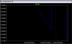
About distortion noone need to worry as 2nd will be in the ballpark -90dB at a realistic 2Vrms input/output.
* A Collection of Potentiometers
* ==============================
* Helmut Sennewald, 12/23/2003 V1.1
*
* Models:
* potentiometer old style LTSPICE potentiometer
* pot_lin k*x
* pot_pow x^k
* pot_plog exp(k*(1-x))
* pot_nlog exp(kx)
* pot_tab table(x)
* pot_piher_plog piecewise linear, datasheet
* pot_radiohm_plog piecewise linear, measured
*
*
* 1 ____ 1.0=wiper
* |
* | | 3
* | |<---- wiper 0..1
* | |
* Rtap | | Tap
* | |
* 2 ____| 0.0=wiper
*
*
* RTOT = total resistance
* WIPER = ratio of travel of the wiper
* RTAP = reference resistance at wiper=Tap
* It is needed only for pot_plog, pot_nlog and pot_pow.
* RTAP is measured between pin-2 and wiper.
* TAP = ratio of travel when Rtap is reached
*--------------------- The Linear Potentiometer ---------------------
*
* 1.0 <----- 0.0
* |3
* __V__
* 1--|_____|--2
*
* o--R1-o-R2--o
*
.SUBCKT potentiometer 1 2 3
* Parameters: Rtot, wiper
.param w=limit(0.01m,wiper,0.99999)
*
R1 1 3 {Rtot*(1-w)}
R2 3 2 {Rtot*(w)}
.ENDS
*
.SUBCKT pot_lin 1 2 3
.param w=limit(0.01m,wiper,0.99999)
*
R1 1 3 {Rtot*(1-w)}
R2 3 2 {Rtot*(w)}
.ENDS
*------------- The Ideal Power Function Potentiometer ---------------
*
* It is interesting to know that the power log. curve is a
* good fit to so called "log"-potentiometers, because most of
* them have not true logarithm dependency in reality.
*
* 1.0 <----- 0.0
* |3
* __V__
* 1--|_____|--2
*
* o--R1-o-R2--o
*
* RTAP is resistance at travel TAP
* Example: Rtot=10k, R=1k @ 0.5 (half way)
* RTAP=1k, TAP=0.5
* RTAP and TAP define a point of the curve resistance versus ratio.
*
.SUBCKT pot_pow 1 2 3
* Parameters: Rtot, wiper, Rtap, Tap
.param w=limit(0.01m,wiper,0.99999)
*
.param pwrexp=ln(RTAP/RTOT)/ln(TAP)
.param ratio=w**pwrexp
*
R1 1 3 {Rtot*(1-ratio)}
R2 3 2 {Rtot*(ratio)}
.ENDS
*---------- The Ideal Positive Logarithm Potentiometer --------------
*
* 1.0 <----- 0.0
* |3
* __V__
* 1--|_____|--2
*
* o--R1-o-R2--o
*
* RTAP is resistance at travel TAP
* Example: Rtot=10k, R=1 @ 0.001
* RTAP=1, TAP=0.001
* RTAP and TAP define a point of the curve resistance versus ratio.
*
.SUBCKT pot_plog 1 2 3
* Parameters: Rtot, wiper, Rtap, Tap
.param w=limit(0.01m,wiper,0.99999)
*
.param pwrexp=ln(RTAP/RTOT)/(1-TAP)
.param ratio=exp(pwrexp*(1-w))
*
R1 1 3 {Rtot*(1-ratio)}
R2 3 2 {Rtot*(ratio)}
.ENDS
*---------- The Ideal Negative Logarithm Potentiometer -------------
*
* 1.0 <----- 0.0
* |3
* __V__
* 1--|_____|--2
*
* o--R1-o-R2--o
*
* RTAP is resistance at travel TAP
* Example: Rtot=10k, R=1 @ 0.999
* RTAP=1, TAP=0.999
* RTAP and TAP define a point of the curve resistance versus ratio.
*
.SUBCKT pot_nlog 1 2 3
* Parameters: Rtot, wiper, Rtap, Tap
.param w=limit(0.01m,wiper,0.99999)
*
.param pwrexp=ln(RTAP/RTOT)/(TAP)
.param ratio=exp(pwrexp*(w))
*
R1 1 3 {Rtot*(1-ratio)}
R2 3 2 {Rtot*(ratio)}
.ENDS
* ------------ The Arbtrary(Table) Potentiometer --------------------
*
* 1.0 <----- 0.0
* |3
* __V__
* 1--|_____|--2
*
* o--R1-o-R2--o
*
.SUBCKT pot_tab 1 2 3
* Parameters: Rtot, wiper
.param w=limit(0.01m,wiper,0.99999)
*
.param ratio=TABLE(w, 0,0.01m, 0.1, 0.001, 0.2, 0.003, 0.3, 0.01,
+ 0.4, 0.05, 0.5, 0.1, 0.6, 0.2, 0.7, 0.35,
+ 0.8, 0.6, 0.9, 0.9, 0.95, 0.98, 1.0, 0.99999)
*
R1 1 3 {Rtot*(1-ratio)}
R2 3 2 {Rtot*(ratio)}
.ENDS
*---------- A Positive "Logarithm" Potentiometer from PIHER ---------
*
* PIHER shows three piecewise linear functions in their datasheet
* for the resistance dependenncy.
*
* 1.0 <----- 0.0
* |3
* __V__
* 1--|_____|--2
*
* o--R1-o-R2--o
*
.SUBCKT pot_piher_plog 1 2 3
* Parameters: Rtot, wiper
.param w=limit(0.01m,wiper,0.99999)
*
.param ratio=TABLE(w, 0,0.01m, 0.05,0.01m, 0.33,0.04, 0.66,0.16,
+ 0.95,0.99, 1.0,0.99999)
*
R1 1 3 {Rtot*(1-ratio)}
R2 3 2 {Rtot*(ratio)}
.ENDS
*--------- A Positive "Logarithm" Potentiometer from RADIOHM. -------
*
* RADIOHM shows a smooth "logarithm/power" curve in the datasheet.
* My own measurements on a 100kOhm stero pot has shown that it
* consists of five piecwise linear sections.
*
* 1.0 <----- 0.0
* |3
* __V__
* 1--|_____|--2
*
* o--R1-o-R2--o
*
.SUBCKT pot_radiohm_plog 1 2 3
* Parameters: Rtot, wiper
.param w=limit(0.01m,wiper,0.99999)
*
.param ratio=TABLE(w, 0,0.01m, 0.1,0.01m, 0.3,0.012, 0.42,0.047,
+ 0.52,0.105, 0.64,0.25, 0.95,0.99999, 1.0,0.99999)
*
R1 1 3 {Rtot*(1-ratio)}
R2 3 2 {Rtot*(ratio)}
.ENDS
For practical reasons I use pot_lin. Do you also need asy´s?
Off course you should avoid the sand-version! But not everyone can afford a good choke.
Still bootstrap with input cap has no meaning at all with the correct choke. Overpopulated ;-)!
About distortion noone need to worry as 2nd will be in the ballpark -90dB at a realistic 2Vrms input/output.
Last edited:
LL1668 gapped 50 mA maybe http://www.lundahl.se/pdfs/datash/1667_68.pdf windings in series 100H 680 DCR
http://www.diyparadiso.com/price/transfo/LLchoke.htm
http://www.diyparadiso.com/price/transfo/LLchoke.htm
Last edited:

Well I choosed to make a "livingroom proto" instead since I have kids running around. I'm always nervous mounting touchable HV stuff in the livingroom. I made it like a AZ1 - 30 uF motorrun - 10H - 50 uF motorrun common chassie and then I made some plates to fit for different configs.

First out is the 6V6 chokeloaded CF. It sticks a 2,2R and double 47 uF for each channel. Abour 255 on the anode.

It playes right now and it has a clearly stiffer bass then my former passive. Nice voices too but still a hum and some other disturbances. 99 dB speakers is not nice to me. I will clear up the hum and get back to you with some measurements once I get sober. It will happen any month now.
Best
Staffan
First out is the 6V6 chokeloaded CF. It sticks a 2,2R and double 47 uF for each channel. Abour 255 on the anode.
It playes right now and it has a clearly stiffer bass then my former passive. Nice voices too but still a hum and some other disturbances. 99 dB speakers is not nice to me. I will clear up the hum and get back to you with some measurements once I get sober. It will happen any month now.
Best
Staffan

My new speakers I'll be HE Altec based setup. In this situation is Cf recommeneded over standard. It will be driving variety is pass amps ranging from 15-20dB of gain.
I think this is promising. Thing is that carefulness is needed around a clean ground to, since its a CF. I will up an LL common mode choke b4 anode and ground but I'm not that sure how to mount it in the C-L-C-L-C chain. What happen if I mount it between the last C-C? Can that cause grounding issues? Well, I'll try and find out
/S
- Home
- Amplifiers
- Tubes / Valves
- 6V6 line preamp