In the spirit of DIY
To the original question, is cable burn in required, in my experience it is not significant. In any event let the system run for 3 days and it will be over.
To my ear, interconnect cables do make a significant difference in the sound. Spending money is not required as DIY cables can easily be heard. For those that are interested in one DIY'ers experience, I clearly prefer solid silver. I settled on 3 strands of 28 gauge for the + and one 24 gauge for the return. Five nines pure silver can be purchased dirt cheap at a jewelry supply store. Myron Toback jewelry supplies in NY has been my source.
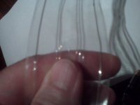
A simple but effective layout is using packing tape to keep the + & neg about 1/2 inch apart. If in doubt about the silver vs copper make one of each and try them both. You will clearly hear the difference but your preference will be your own.
And yes, it does make an impact if you use solid silver for the signal wire throughout your system.
To the doubters, please remember that this is DIYAudio.com, not PureEngineeringAndYouBetterProveItInaDoubleBlindTestOrElseAudio.com
To the original question, is cable burn in required, in my experience it is not significant. In any event let the system run for 3 days and it will be over.
To my ear, interconnect cables do make a significant difference in the sound. Spending money is not required as DIY cables can easily be heard. For those that are interested in one DIY'ers experience, I clearly prefer solid silver. I settled on 3 strands of 28 gauge for the + and one 24 gauge for the return. Five nines pure silver can be purchased dirt cheap at a jewelry supply store. Myron Toback jewelry supplies in NY has been my source.
A simple but effective layout is using packing tape to keep the + & neg about 1/2 inch apart. If in doubt about the silver vs copper make one of each and try them both. You will clearly hear the difference but your preference will be your own.
And yes, it does make an impact if you use solid silver for the signal wire throughout your system.
To the doubters, please remember that this is DIYAudio.com, not PureEngineeringAndYouBetterProveItInaDoubleBlindTestOrElseAudio.com
Attachments
You will clearly hear the difference
What if we don't?
What if we don't?
Worst case, you have invested and hour and whatever $ the silver and copper cost and proven that it makes no difference to you. If the risk of that outcome is too much, then best to avoid it.
") Ideally find a friend to give your the silver as it is only cheap when you buy an ounce which will last a lifetime.
Ideally find a friend to give your the silver as it is only cheap when you buy an ounce which will last a lifetime.
Last edited:
People often say that, and it sounds 'scientific', but I am not convinced it is true.Galu said:It may be useful to point out that the bulk of the energy transmitted by a cable is not carried by the moving electrons, but by the electromagnetic fields which surround the conductors.
Consider a cell with 1V supplying 1A via a pair of wires to a 1 ohm resistor. If you evaluate the normal component of the Poynting vector on a closed surface surrounding the cell you will find that 1W leaves this surface. Similarly, 1 W enters a surface surrounding the resistor. It might seem obvious that evaluting things in between woukd show a net flow of 1W. The snag is that you need a closed surface for Poynting's conjecture to be used. Any closed surface in between would give a value of zero.
People then try to fall back on just looking at the Poynting vector itself, but this doesn't actually tell us anything useful. You will find that it just swirls around in circles.
The energy going from the cell to the resistor is actually carried by the potential energy of the electrons in the wire. When they reach the resistor this potential energy is turned into kinetic energy as they fall down the voltage gradient, and the kinetic energy is then turned to heat as they hit lattice faults in the resistor.
Only for a bad interconnect (or perhaps a very long one) and poorly-engineered sources or loads.This filtering action can explain such observations as the increase or loss of high frequencies upon changing an interconnect.
That layout is simple and effective only if your aim is to increase RF pickup, and the consequent spurious 'sparkle' and 'detail' in the sound. Thanks for helpfully illustrating what I often say: DIY cables are usually poorly designed (as cables).wlowes said:To my ear, interconnect cables do make a significant difference in the sound. Spending money is not required as DIY cables can easily be heard. For those that are interested in one DIY'ers experience, I clearly prefer solid silver. I settled on 3 strands of 28 gauge for the + and one 24 gauge for the return. Five nines pure silver can be purchased dirt cheap at a jewelry supply store. Myron Toback jewelry supplies in NY has been my source.
A simple but effective layout is using packing tape to keep the + & neg about 1/2 inch apart.
It is common in HF radio design to vary strands(Litz) and solid diameter. For example a large diameter solid antenna will have greater bandwidth than a small stranded litz.
So if you want a very narrow bandwidth antenna then, in addition to tuning resonance you can also design for narrow or wide bandwidth using wire geometry.
So if you want a very narrow bandwidth antenna then, in addition to tuning resonance you can also design for narrow or wide bandwidth using wire geometry.
If the risk of that outcome is too much, then best to avoid it.
People keep making that assumption with no evidence,
That layout is simple and effective only if your aim is to increase RF pickup, and the consequent spurious 'sparkle' and 'detail' in the sound. Thanks for helpfully illustrating what I often say: DIY cables are usually poorly designed (as cables).
Happy to make your day
Actually, I do not disagree with your observation. No question more prone to RF pickup and fragile compared to commercial stuff. It is possible this causes the sound I prefer. But I find that commercial shielded the cable always seems to kill the sound. Each to their own.
Litz has nothing to do with it.It is common in HF radio design to vary strands(Litz) and solid diameter. For example a large diameter solid antenna will have greater bandwidth than a small stranded litz.
So if you want a very narrow bandwidth antenna then, in addition to tuning resonance you can also design for narrow or wide bandwidth using wire geometry.
It's the diameter to length ratio that's important.
Many HF antennas are hollow tubes.
Wide bandwidth can be good or bad, depending.
They say lots of things.They say not all sound we hear can be measured.
Audio enthusiasts are given to reporting any number of things.
Art Dudley :: Stereophile Magazine
* * * * * * * * *
Yet any differences that they can hear, can be measured.
The best cable i invested in was to run a radial circuit 6mm t&e cable from the mains distribution board direct to the sockets feeding my HIFI.. It eliminated 12 joints in the cable as it was on a ring main previous to this. Imagine having twelve joints in any
of your interconnects! Anyway all my interconnects sounded much better for it. As it goes my source, amplifier and speakers sounded better too.
of your interconnects! Anyway all my interconnects sounded much better for it. As it goes my source, amplifier and speakers sounded better too.
Last edited:
People then try to fall back on just looking at the Poynting vector itself, but this doesn't actually tell us anything useful. You will find that it just swirls around in circles.
The Poynting vector is used to show the direction of the energy, and hence signal, flow in a cable.
The current in the cable sets up electric and magnetic fields around the two conductors which make up the cable. The electric field lines always cross the magnetic field lines at right angles.
By application of the right hand rule, the direction of the Poynting vector is shown to be at right angles to both the electric and magnetic field lines.
If we assume the current flow in the signal conductor to be away from us, then the direction of the Poynting vector is also away from us, down the length of the conductor.
When the current reverses direction, as it does in an ac signal, the Poynting vector's sign remains unchanged, as both the electric and magnetic fields surrounding the cable change direction simultaneously.
Hope it has helped by 'Poynting' this out, but now my head is going round in circles!

Imagine! How did you get rid of the hundreds of joints in your amplifers?
He smoked them.
- Status
- This old topic is closed. If you want to reopen this topic, contact a moderator using the "Report Post" button.
- Home
- Member Areas
- The Lounge
- Silver RCA Cable-share your experience, opinions here!