I wish someone would come up with a new reason to hate NFB (Real-Time Error Prevention) http://www.diyaudio.com/forums/solid-state/317976-amplifier-sound-force-7.html#post5373659
Does this comedian have any other material we can read?
6loons is full of reviews like that. If you can find the text amongst the forest of adverts.
I do not understand this NFB obsession and no GNFB adoration, especially in power amplifiers. In power amplifiers with no GNFB we usually only get high output impedance + high distortion = sound coloration. This is preferred? Really?
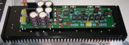
Let me put one example. About 5 years ago I built an AYRE-V3 clone, no GNFB fully balanced amplifier, all MOSFET, with complementary-differential input. We had a listening session, about 20 people, and I did not inform anybody what is in the box. Just standard amplifier 3U 19" amplifier box with side fin heatsinks, looking like many other amplifiers. No one in the room preferred this amplifier, by listening. No one, till now, has known what topology was tested.
The only very good result I had with no GNFB power amplifier was purely classA power amp with strong NFB inside the output stage, that measured below 0.001% THD everywhere and had reasonably low output impedance like 0.1 ohm.
Attachments
Last edited:
PMA, I kind of agree with you about the difficulty in making a successful open loop power amp, however I know that open loop preamps and phono stages can be very successful and still have pretty good measurements. Perhaps not the lowest in the industry, but 0.01% max at working levels and usually much less is practical and possible. I do it with the CTC Blowtorch, and subjectively this preamp sounds better than any other preamp that I have designed (and I have designed several) before or since. But in commercial practice, I use some feedback, and like you, like to use as high open loop bandwidth as I possibly can as well, just like Matti Otala suggested almost 50 years ago.
I have read through several chapters of Dostal's 'Operational Amplifiers' textbook and found it based mainly on American manufacturers app notes, mostly Silicon Valley, as I suspected it would be. I had hoped for more Russian influence, but I have not found it yet. However, Jiri Dostal has made some of his own contributions that I think are very worthwhile, one that you put up here previously based on a Hybrid containing a UA709 and discrete transistors. It shows impressive design ability over and above typical engineering capability.
I have read through several chapters of Dostal's 'Operational Amplifiers' textbook and found it based mainly on American manufacturers app notes, mostly Silicon Valley, as I suspected it would be. I had hoped for more Russian influence, but I have not found it yet. However, Jiri Dostal has made some of his own contributions that I think are very worthwhile, one that you put up here previously based on a Hybrid containing a UA709 and discrete transistors. It shows impressive design ability over and above typical engineering capability.
I'm not sure to have understood what you said Or, may-be it is you ?
The question was extracting the error signal of a device witch has gain using a comparateur connected to input and output pins.
What feedback are-you talking about ?
I think we talk about the same circuit, if I remember correctly it was a differential to single ended stage? If I am wrong, could you post a schematic of what you were addressing?
Jan
Let me put one example. About 5 years ago I built an AYRE-V3 clone, no GNFB fully balanced amplifier, all MOSFET, with complementary-differential input.
[snip]
No one in the room preferred this amplifier, by listening.
It is too late to check now but I would be willing to bet a lot of money that the results would have been quite different if the amp had been in a standard flashy Ayre Acoustics enclosure.
Jan
It is too late to check now but I would be willing to bet a lot of money that the results would have been quite different if the amp had been in a standard flashy Ayre Acoustics enclosure.
Jan
Hello Jan, yes, maybe. And maybe not. The audience were our hifi enthusiasts who have quite a lot of experience with low distortion amplifiers and do not care much about product appearance. Their objections to the amplifier sound were quite similar to my own. Maybe your guess would fit to different audience
 .
.To see how "good" the V3 was, please check Stereophile review
Ayre Acoustics V-3 power amplifier | Stereophile.com
I can confirm their measurements.
I do not understand this NFB obsession and no GNFB adoration, especially in power amplifiers. In power amplifiers with no GNFB we usually only get high output impedance + high distortion = sound coloration. This is preferred? Really?
Let me put one example. About 5 years ago I built an AYRE-V3 clone, no GNFB fully balanced amplifier, all MOSFET, with complementary-differential input. We had a listening session, about 20 people, and I did not inform anybody what is in the box. Just standard amplifier 3U 19" amplifier box with side fin heatsinks, looking like many other amplifiers. No one in the room preferred this amplifier, by listening. No one, till now, has known what topology was tested.
The only very good result I had with no GNFB power amplifier was purely classA power amp with strong NFB inside the output stage, that measured below 0.001% THD everywhere and had reasonably low output impedance like 0.1 ohm.
I built a preamp (GainWire mk2) where is possible very simply to switch between non GNFB and quite high CFA (abouth 40dB). It has quite low distortion in non GNFB mode, and very low in CFA mode. I've sell some PCBs and some of the builders preferred non GNFB mode and some CFA mode.
I myself could not say what I prefer, probably to old ears.
And yes, it has a headphone output too and possible to compare without power amp with good headphones.
Damir
Your way to build it into a neutral case is a good one.
Jan
I hope so
. As well as not telling what is inside. It is the only way to do the tests.Could you just clarify, John: is it low/zero NFB which characterises "serious audio designers" or high hopes?john curl said:I am working on an all open loop phono preamp, like Charley Hansen did before me. AND an extremely low nfb I-V converter (I have to make the distortion slightly lower than the phono because of the different operating points), and I have high hopes. This is what serious audio designers do!
I think Jan misunderstood what you said. I believe you were talking about the need to equalise frequency response if you wish to use subtraction to compare input and output, but Jan thought you were talking about subtraction as part of the feedback loop.Tournesol said:I'm not sure to have understood what you said Or, may-be it is you ?
The question was extracting the error signal of a device witch has gain using a comparateur connected to input and output pins.
What feedback are-you talking about ?
Strangely familiar some how......... Oh! Prez Trump !

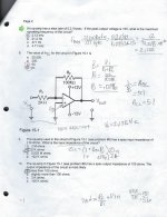
My last instructor said the following when I pointed out the OpAmp diagram he depicted
was incorrect and that I solved it correctly based upon the faulty diagram.
Did this problem have to do with noise gain?
Actually it is fairly easy to take a guess at the sound... but these are comments with one specific amp, one where no one prefers over 30% gnfb, and most are at 0% or 10%.
No-gnfb, how about ngf for short... Consider that in an SS device this can mean that the higher hz phase can be stumbling around like a drunk. This may enhance 2HD, but it at least encourages a similar blur effect as purposely introducing high RF (like a grounding box). So it is beneficial to mask moronic mix/mastering mistakes like raw hard left/right panning that make you think a guitar player suddenly lives in your speaker cabinet. It also makes bass warmer and more realistic. Its more realistic because a dampened speaker and room doesnt vibrate, but ngf makes it sound like stuff is vibrating sense it isnt so tight in sound, and gets that blur effect on the higher hz information that accompanies the lower hz fundamental...
It does not seem to expand the soundstage like you would get with a grounding box.
Using hgf (100%) suddenly can make the bass sound defined, powerful, but small and isolated. It literally takes you out of the music, and makes you feel like you are examining something. Mistakes in the mix/master shout out "over hear, isnt it great how I sound shitty like I am half a reflection from a wall in the studio" or many others, that make you want to faceplant into palm. You may also find out just how tuned in a particular direction speakers or such could be, like higher tweeter levels...
Obviously this would be different on some hot tubes, and hot classA SS may not exhibit as much difference. I suspect with tubes the character changes may be pretty different. From the tube stereos I have heard, it would seem a little apple to orange for what gnfb sounds like.
I don't necessarily feel comfortable getting into a "sound" due to XYZ, but I appreciate where you're coming from. I'm way more comfortable in control theory.
My concern is that, like PMA referred, one could ostensibly overbuild (especially the OPS to knock out crossover distortion) to get low output impedance over pretty wide bandwidth and generally a product that would perform like it is leveraging a decent amount of global feedback. There's also just a lot more gain hanging around to locally linearize each stage with (appropriate) transistors than tubes, like-for-like. Isn't Valery here on DIYAudio making some pretty crazy low-distortion amps with minimal-to-no global feedback? I'd expect that to sound a lot different to other types which exhibit a more SET-like performance.
In other words, it'd be interesting to listen to a variable global feedback amplifier to see if you like it at some operating parameter (and resulting performance) to another, but, as you say, it'd be relevant to that amplifier. Then you could carefully characterize the amp at that setting and go about aiming for a similar performance profile.
I am not sure if I've looked at Valery, may have to... I'd suspect the benefits be in making the speakers to perform better (as opposed to accuracy to source), in such a way it would reduce some need for gnfb. Is that "nested" ? I'm not sure what the qualifiers for the term "nested" is other than it isn't global. I'm curious about the sound as well. Does it make things retain or lose blur, but not increase resolution? Does it just make it a little more linear but not gain resolution or refinement against the blur effect? These are not easy answers since so many amps cannot simply switch feedback settings. Without getting to play with changing settings on an amp, it was all pretty well speculation for me prior, but doing so did confirm a decent amount of what one would assume (at least for an SS amp).
In all this I think some generalizations can be taken, because of some consistency with sound and preferences. For example MSB's amplifiers are classA, and with no feedback they sound considerably different than turning it off on the classAB I was playing with (CH M1, btw). The difference is more with the class than the feedback, I'd say, since classA typically has familiar character between a hell of a lot of amps & is no where to be found on the M1 without climbing gnfb (although for each gain there may be a loss, trying to get to ngnfb classA sound). And yet both exhibit some blur so that you dont have an etched or overally hardened image. This is probably since the classA doesnt shed all of its linearity like AB declining in gnfb - so to me it doesnt sound as flat.
The biggest noticeable thing was as I said earlier, how bad bass can be in a room that can't vibrate, with speakers to heavy to vibrate, etc... It sounds so small that my pals answer is to incorporate 2 JL Gothom dual 12" with 6500w amps or whatever.... because he is craving immersion. It isnt because the bass measures low, it is because we cant hear it so much and need tactile sensation. My thought now is that suspended floors for everywhere but the component rack and speaker placement makes perfectly sense, to allow a tactile response to be felt in your feet and chair.
PS. I would have told him to get Funk Audio subs for the real low end, but JLs are literally everywhere in the high end community. Shipping DESTROYED one of them, but JL was really good about it and sent out a replacement that day, so props to customer service.
No, it was the opamp closed loop gain, Acl.Did this problem have to do with noise gain?
Okay I found the question. The opAmp was reversed than what I said previously. It's attached. The problem for me was this;
The first day of class, instructor Y says, the course book is Floyd, T. (2015). Electronic Devices: Electron Flow Version,. 9th ed. Pearson Education. Then he asks if everyon has the Boydell. Laboratory Manual to accompany Electronic Devices and Circtuits 7th ed. Prentice-Hall.?
Ask's use to look online for it. (No one could find it or the Boydell, Paynter EDC 7th ed nor the lab manual.) The set up. So we go though the Floyd book in class, lab, homework, etc. Handouts are from Boydell.... Turns out the tests were from Paynter's test bank.
AND the test was open book. It didn't matter because the test items weren't found in Floyd's book and the wording is just enough so you go WTF with some of the questions... The diagrams are different also.
Any way here is what I had issue with. It would be (1/B) -1 = Acl if Inverting. With Vin right next to the ground terminal, 1/b = Acl if non-inverting, Solving for it wasn't the issue. So just to clarify, I wrote in pencil how I viewed the signal input.
Attachments
Last edited:
The problem for me was this
The answer to question #8 is -50 times, so none of the supplied answers were right.
Last edited:
Well I'll be.
He was telling me that there are invisible connections, that is what the open terminals mean. If Vin was in series with Ri , I would have calculated it for an inverting input.
I don't like Floyd's book isn't that good. With all the practice, problems, etc in the book directing you to Peraron Education website for solutions and examples-- Pearson doesn't have them for the book on their website...imagine that.
I bought an older version of Paynter, Boydel Electronic Devices and Circuits and found it was an excellent text.
Last edited:
- Status
- Not open for further replies.
- Home
- Member Areas
- The Lounge
- John Curl's Blowtorch preamplifier part III