On the chance that you were asking me..Pls include at what freq tests were made regarding inductance and/or thd or H3. H3 can also vary with freq. so more than one freq is required for audio applications. Thx-RNMarsh
I tested inductance at 100, 120, 1Khz, 10Khz, and 100Khz using an HP meter.
My lower test value obtainable at 100 Khz is 250 pH, this while trying to measure a resistor designed to 60 pH. While I suspect the added inductance is a result of the current spreading along the plates to all the resistors, I've not taken the effort to eliminate that.
I've not measured H3 nor thd, as I've no AP. Hence my interest in having Ed perform some specific tests.
Trying for values below half a nH will probably have to use Mhz drive with kelvin taps magnetically central to the resistor. Not hard by the way, I'm doing it right now on the next .1 ohm cvr I'm making.
jn
Last edited:
alum 6061-T6 is (or used to be) readily available formed into standard rack sized chassis panels for custom chassis assembly... such as top and bottom cover, front/rear panels, sides. Esp useful for racks full of chassis to keep total loaded rack weight down. Light weight and very strong. -RNM
Wishing to avoid Yet Another Fourier Debate I note that, as far as I am aware, proximity effect does not create IM in RF engineering so it is unlikely to do it for the much lower frequencies of audio. Proximity effect does increase losses, but loss is a linear phenomenon. The most it might do in audio is increase any thermal distortion in resistors at high frequencies by concentrating the current a little, yet at HF there is little thermal distortion because of the thermal time constants of the resistor.
So not a distortion mechanism, but perhaps a minor increase in another (rather tiny) distortion mechanism.
So not a distortion mechanism, but perhaps a minor increase in another (rather tiny) distortion mechanism.
About resistance distortion, i think the only interesting measurement would be, on a VERY low distortion amplifier, to try various resistance and see how they Realy affect its distortion.
And try to correlate with listening.
How can-we be sure that feedback resistor own distortion does not compensate some amp distortion instead of increase-it ? (I do not believe-it, but the question remains)
Once again, we have to consider the whole system. And get an idea of the order of magnitude.
And try to correlate with listening.
How can-we be sure that feedback resistor own distortion does not compensate some amp distortion instead of increase-it ? (I do not believe-it, but the question remains)
Once again, we have to consider the whole system. And get an idea of the order of magnitude.
Wishing to avoid Yet Another Fourier Debate I note that, as far as I am aware, proximity effect does not create IM in RF engineering so it is unlikely to do it for the much lower frequencies of audio. Proximity effect does increase losses, but loss is a linear phenomenon. The most it might do in audio is increase any thermal distortion in resistors at high frequencies by concentrating the current a little, yet at HF there is little thermal distortion because of the thermal time constants of the resistor.
So not a distortion mechanism, but perhaps a minor increase in another (rather tiny) distortion mechanism.
I believe you to be incorrect.
The bridge described will locate it if it exists. Ed?
jn
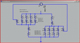
my very simplified model of a lumped "proximity effect" simulation
inductance, mutual inductance K values pulled out of thin air - just illustrating the principle
the diff V is going to linear to limits of the materials electrical parmeters linearity - for the spice models, the fft is limited by numerical resoution at about -180 dB with default LTspice fft settings
Attachments
Last edited:
I believe you to be incorrect.
The bridge described will locate it if it exists. Ed?
jn
A weekend project, right now we are finishing up 9 racks for a stadium. 98 amplifiers, about half are 5kW the rest 2Kw. AES over fiber distribution with 600 ohm transformer isolated backup.
skin effect.... micro-details
useless information dept --> skin effect of circular conductors has the inductance lowest at or near the surface for HF. Thus, those currents flow or are denser there. On a single pcb trace the HF flow at the outer edges. Edge irregularities from etching causes the path length to be longer for HF. Any sharp corners or edges increases the L at that point. These things matter in high current, fast rise pulse fidelity. FYI. - RNMarsh
useless information dept --> skin effect of circular conductors has the inductance lowest at or near the surface for HF. Thus, those currents flow or are denser there. On a single pcb trace the HF flow at the outer edges. Edge irregularities from etching causes the path length to be longer for HF. Any sharp corners or edges increases the L at that point. These things matter in high current, fast rise pulse fidelity. FYI. - RNMarsh
Last edited:
George,
100 W 6 ohms (?) P=E^2/R = Vrms=24.5 Vp-p = 69.29 at 10K =.48W Peak but really .06W. At 8 ohms Vrms=28.28 P=.08W
Thank you Ed.
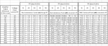
The 1.414 multiplier on second column fell into the glass of Ouzo and lost it’s senses.
I attach the corrected table.
So with a KOA/Speer 1/4W 10K Carbon film resistor I would expect .00052% distortion @100 Hz. from the feedback resistor. The LM4562 lists it's distortion as .0003% so the resistor is not as good as the "Horrible" opamp.
From here,
http://www.ti.com/lit/ds/symlink/lm4562.pdf
distortion is listed as 0.00003% -0.00009% (5th decimal place) at 4V out, 600-10KOhm load and the measurement is conducted with a 1K Rf (see Fig.4 for the trick used to measure such low distortion), thus this figure should logically include the distortion produced due to Rf.
Apart from this, how do you perform the resistor distortion calculations?
George
Attachments
Thank you Ed.
The 1.414 multiplier on second column fell into the glass of Ouzo and lost it’s senses.
I attach the corrected table.
From here,
http://www.ti.com/lit/ds/symlink/lm4562.pdf
distortion is listed as 0.00003% -0.00009% (5th decimal place) at 4V out, 600-10KOhm load and the measurement is conducted with a 1K Rf (see Fig.4 for the trick used to measure such low distortion), thus this figure should logically include the distortion produced due to Rf.
Apart from this, how do you perform the resistor distortion calculations?
George
George,
I have looked at how they do the distortion measurements and I think they are in error! I think most of what they are seeing is still from the resistors.
I assume you understand my 10 resistor method to measure the distortion. From there it is 3 db more per octave of lower frequency for the third harmonic and 6 db more for each doubling of voltage. Straight power law!
As I test at 1000 Hz the distortion goes up by 10 db at 100 Hz and if for some reason you want to use 20 Hz add another 7 db. My test voltage is 7 volts. The other factor is since I am comparing the resistor to identical units at 1/2 power you must add another 3-6 db for the uneven voltage divider effect. And as I have mentioned if you use the other resistor in the divider with a different thermal time constant you can add another 50 dB for the music to ear compensation!
So enjoy the Ouzo. Also note almost no one else even understands what we have been discussing!
useless information #2:
a bit more on skin effect in PCB traces, the ground proximity effect further down is quite interesting:
Printed Circuit Design & Fab Magazine Online
a bit more on skin effect in PCB traces, the ground proximity effect further down is quite interesting:
Printed Circuit Design & Fab Magazine Online
We just have to be careful to remember that lack of 'pulse fidelity' is not the same as non-linear distortion. A linear filter can change pulse shape.RNMarsh said:These things matter in high current, fast rise pulse fidelity.
Proximity effect is not linear. Why is that being assumed???
When the current in the lead is causing proximity dependent current redistribution, the equation is of the form:
effect = K(onstant) times (dI/dt)squared.
When the current is rising positive, the current profile of the the cylindrical resistor current will try to take the lowest impedance path, which is as close to the outside lead near the body as the current can to.
When the current is falling negative, the current profile of the the cylindrical resistor current will try to take the lowest impedance path, which is as close to the outside lead near the body as the current can to.
Note that no matter which way the current is changing, the end effect is the current will redistribute in the same direction. The faster the absolute value of the slew, the higher the resistance...
Nice model. However, there is no good way to simulate a field modified resistance. You can include inductive coupling, but not the variation of resistance with slew rate. And, see above, you need some ideal rectifiers in there.
However, that has nothing to do with the proximity effect I speak of..
Perhaps over the weekend Ed can try.
jn
When the current in the lead is causing proximity dependent current redistribution, the equation is of the form:
effect = K(onstant) times (dI/dt)squared.
When the current is rising positive, the current profile of the the cylindrical resistor current will try to take the lowest impedance path, which is as close to the outside lead near the body as the current can to.
When the current is falling negative, the current profile of the the cylindrical resistor current will try to take the lowest impedance path, which is as close to the outside lead near the body as the current can to.
Note that no matter which way the current is changing, the end effect is the current will redistribute in the same direction. The faster the absolute value of the slew, the higher the resistance...
my very simplified model of a lumped "proximity effect" simulation
Nice model. However, there is no good way to simulate a field modified resistance. You can include inductive coupling, but not the variation of resistance with slew rate. And, see above, you need some ideal rectifiers in there.
Agreed. And, there is no internal magnetic field with a cylindrical sheet of current.useless information dept --> skin effect of circular conductors has the inductance lowest at or near the surface for HF. Thus, those currents flow or are denser there.
However, that has nothing to do with the proximity effect I speak of..
Perhaps over the weekend Ed can try.
jn
Last edited:
useless information #2:
a bit more on skin effect in PCB traces, the ground proximity effect further down is quite interesting:
Printed Circuit Design & Fab Magazine Online
THANK YOU.
Everybody look at figure 3.
edit: Two other notes.
1. The author invokes HoJo. In his book, I think it was the '94 edition of high speed signal..., he intro'd a picture depicting the toroidal current loops which are cause by the inner magnetic fields of the conductor during current slew. At DC, the internal magnetic field is zero at center, and rises linearly to peak at conductor surface. During slew, this internal field creates the toroidal currents which are of a sign such that at the center it opposes bulk current flow, and enhances the outer surface bulk flow. I introduced this depiction back in '92 on some site, I think it was AH..
2. Figure 5 depicts the skin resistance in the T-line model as a simple resistor. It is in fact a time dependent resistor, depending on slew rate at any instant in time. A simple resistance is an approximation, as the actual value would be an extremely difficult one to use.
Last edited:
Thanks a lot, gpapag.distortion is listed as 0.00003% -0.00009%
It means around -120/-130db... hum...
Since two days i was not sleeping by night, because all those nightmares of horrible distortions...
I will sleep tonight and dream of pink resistances...
George,
I have looked at how they do the distortion measurements and I think they are in error! I think most of what they are seeing is still from the resistors.
!
Excuse me, these numbers are at G = <PLUS>1, the distortion making resistors must be imaginary. There is no current flowing in Rf in figure 4 save the (101x the error signal)/Rf. Come on guys, pay attention. Ed you mis-understood my joke, you said the thermal distortion was third order for a DRY resistor.
")
Last edited:
We just have to be careful to remember that lack of 'pulse fidelity' is not the same as non-linear distortion. A linear filter can change pulse shape.
generally true but only for a certain set of conditions. The delay caused by skin effect between low and high freq contained in a data pulse causes trouble with waveform shape which affects the data flow integrety. Timing circuits as well. Group delay and perhaps jitter as well [indirectly]. We arent living in just an analog music world.... well maybe we are in this thread. Thx-RNMarsh
useless information #2:
a bit more on skin effect in PCB traces, the ground proximity effect further down is quite interesting:
Printed Circuit Design & Fab Magazine Online
Note I was careful to say - on a single pcb trace. That means without ground planes... which distributes the skin effect differently. But edges and sharp corner affects are still in affect. Thx-RNmarsh
Last edited:
Proximity effect is just the mutual version of skin effect (i.e. self-proximity). Skin effect is linear, therefore proximity effect is too.jneutron said:Proximity effect is not linear. Why is that being assumed???
We seem to be getting dangerously close to YAFD.RNMarsh said:generally true but only for a certain set of conditions.
- Status
- Not open for further replies.
- Home
- Member Areas
- The Lounge
- John Curl's Blowtorch preamplifier part II