The situation was getting confusing, even for me, so I called Ed Simon. Five minutes and I NOW understand.
First of all, what is important primarily is the OVERSHOOT (upward pulse) difference between 'fast' and 'standard' diodes. Everyone, look carefully at the pictures in 54538.
It must be understood that several decades ago, we did not consider using high speed diodes for 60Hz operation. We thought they were only important for switching power supplies, where the working frequencies were 20KHz and above. I was fooled, until my colleague, Rick Miller showed me differently.
YET, it was difficult to get the information out, as Rick was not a known 'audio designer' so even his inputs to TAA would be resisted. (It happened to me with WW, back in 1971, in the same way.) So Walt Jung and I coaxed Ed Dell to show Rick Miller's findings. Since then, EVERYBODY knows about diode problems at 60Hz '-)
Thanks John.
I doubt it.
You've no experience with this specific aspect of testing diodes, nor circuit topologies necessary for very high slew rate currents.
I do not suffer that lack of experience. I offer it.
ps..just a note: the fast recovery diodes will have pretty much the same overshoot as the 4007, but it transits much faster. The ferrite absorbs most of the faster transition, and the parasitics of the loose winding coupled with the big loop to the unmatched coax kills the rest. These tests need some serious RF design techniques, the way ed made the first setup is leading you down the wrong path blindly.bad test setups give bad results, and lead to bad conclusions.
jn
Last edited:
Good point, BUT that is OK. At least it is not where the 1n4007 is.
Actually it does. The 4007 is spec'd at what, 2 uSec? (don't have the databook handy..) If you look at the loop to the coax, it's going to be in the 2 uH range, which makes the probe signal go all wishy washy. The diode wire loops, same thing..
When the diode flips off in the ten amp per microsecond range, how would you expect those levels of parasitics to react?
As I said, I'd be happy to help out with the design/layout for these kinds of tests, I believe the overall results are very useful to the audio community.
But it'd be nice to actually get accurate results and draw accurate conclusions.
jn
Here are the results of my tests using a ferrite core designed for RF use. As my good Tek scope is down these are from my Owon as it is a 20 Mhz bandwidth scope it will not show all of the energy. I have also shown before the results of RF spectrum and these clearly show spikes around 2 nS duration.
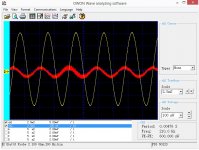
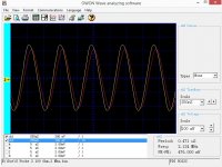
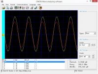
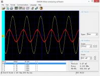
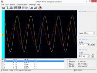
Just for SY, The current source is a function generator set to sine wave (Except for the square wave shot) driving a 100 ohm resistor. Channel 2 (yellow trace) shows the voltage across the resistor. We use Ohm's law to realize the current is 10 mA per volt shown. The Channel 1 input shows the output of the probe and preamp. It is the red line. At the bottom is the particular notes for each shot.
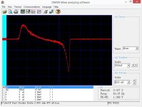
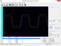
The calibration shows that the core attenuates low frequencies (not very surprising) and the entire system overshoots a bit at 1 Mhz squarewaves. I also include a redo of the Fairchild FAST diodes for a comparison between the much worse proof of concept tests and this better probe. There also is a close up of the turn off surge showing the limits of the system.
JN, I am not looking a diode switch off. I am looking at power supply design going stage by stage.
Just for SY, The current source is a function generator set to sine wave (Except for the square wave shot) driving a 100 ohm resistor. Channel 2 (yellow trace) shows the voltage across the resistor. We use Ohm's law to realize the current is 10 mA per volt shown. The Channel 1 input shows the output of the probe and preamp. It is the red line. At the bottom is the particular notes for each shot.
The calibration shows that the core attenuates low frequencies (not very surprising) and the entire system overshoots a bit at 1 Mhz squarewaves. I also include a redo of the Fairchild FAST diodes for a comparison between the much worse proof of concept tests and this better probe. There also is a close up of the turn off surge showing the limits of the system.
JN, I am not looking a diode switch off. I am looking at power supply design going stage by stage.
Attachments
-
 Probe 2 200 Hz Calibration.jpg156.1 KB · Views: 211
 -
 Probe 2 Fairchild Fast Diodes Turn off close up.jpg128.8 KB · Views: 75
 -
 Probe 2 Fairchild Fast Diodes.jpg129.5 KB · Views: 75
 -
 Probe 2 1 MHz Square wave 100 Ohm.jpg136.6 KB · Views: 174
 -
 Probe 2 2 Mhz Cal.jpg156.6 KB · Views: 205
 -
 Probe 2 200 kHz Cal.jpg155.6 KB · Views: 205
 -
 Probe 2 2000 Hz Cal 100 ohm.jpg159.3 KB · Views: 213
 -
 Probe 2 20,000 Hz Cal.jpg159.4 KB · Views: 72
Last edited:
Excellent results, nice test..Here are the results of my tests
Yah, the transfer function drops as frequency, not surprising as you say. The overshoot is circuit inductance and transition speed. This will rear it's ugly head when you stick a snap diode in. edit: sometimes a diode will hold it's current for a while, then really snap off, while some diodes will be much softer in the transition. It's all that diffusion stuff, and how quickly the charge sweeps out or recombines via diffused or implanted impurities.The calibration shows that the core attenuates low frequencies (not very surprising) and the entire system overshoots a bit at 1 Mhz squarewaves.
I also include a redo of the Fairchild FAST diodes for a comparison between the much worse proof of concept tests and this better probe.
Would you please also redo the 4007...thanks.
JN, I am not looking a diode switch off. I am looking at power supply design going stage by stage.
You'll need to speak to JC then, he has a different take..to wit:
The situation was getting confusing, even for me, so I called Ed Simon. Five minutes and I NOW understand.
First of all, what is important primarily is the OVERSHOOT (upward pulse) difference between 'fast' and 'standard' diodes. Everyone, look carefully at the pictures in 54538.
Well JN, this is not the most important aspect of what Ed is measuring. It is the OVERSHOOT or lack of, that is the point.
But handling the supply design from stage by stage is indeed worthwhile. I like what you're doing..thanks
jn
Last edited:
Here are the results
AH, almost forgot.
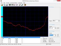
Your first two transfer responses get progressively stranger, at 2Khz it's starting to show those weird artifacts that you presented at 10 KHz previously.
Something is not right somewhere. Don't know where. But my spidey sense is tingling. I think there's some kind of equipment artifact as yet unidentified.
jn
Last edited:
What is the freq response BW of the ferrite core design? -3dB at ?? freqs?
THx-RNMarsh
It is minus 3 db around 20,000 Hz and I don't have a generator to span the frequencies between 2 Mhz and 50 Mhz at the moment. My estimate is it is good to 10 Mhz. Paper calcs say 15.
(I lost everything in Hurricane Ivan 10 years back and only replace gear when I need it.)
AH, almost forgot.
Your first three transfer responses get progressively stranger, at 2Khz it's starting to show those weird artifacts that you presented at 10 KHz previously.
Something is not right somewhere. Don't know where. But my spidey sense is tingling.
jn
Those artifacts are most likely digitization errors. They show up on some sine waves.
Those artifacts are most likely digitization errors. They show up on some sine waves.
Ah, thanks. Perhaps scott can set you up with a fast pre design.
jn
Man, have I said I hate software,Frank, your link is not working
 ?? Dropbox and me just do not get on, every time I use it it does not "compute" ... . "Easy to use" software I hate with a passion, because unless you do things exactly the way it expects you behave, it just goes weird - at least for me ... .
I'm trying this now: https://www.dropbox.com/s/dst85w7eft3ox6t/ChiliPeppers-Californication.wav
Last edited:
It is minus 3 db around 20,000 Hz and I don't have a generator to span the frequencies between 2 Mhz and 50 Mhz at the moment. My estimate is it is good to 10 Mhz. Paper calcs say 15.
(I lost everything in Hurricane Ivan 10 years back and only replace gear when I need it.)
If the probe/pickup response has a rising characteristic vs freq then it will accentuate the highs and maybe contribute to the diode spike amplitude. You can EQ it flat in your preamp.
THx-RNMarsh
Last edited:
Actually it does. The 4007 is spec'd at what, 2 uSec? (don't have the databook handy..) If you look at the loop to the coax, it's going to be in the 2 uH range, which makes the probe signal go all wishy washy. The diode wire loops, same thing..
When the diode flips off in the ten amp per microsecond range, how would you expect those levels of parasitics to react?
As I said, I'd be happy to help out with the design/layout for these kinds of tests, I believe the overall results are very useful to the audio community.
But it'd be nice to actually get accurate results and draw accurate conclusions.
jn
The 1N4007 is supposed to be/was a little different from the others. The note in the link mentions the long recovery time of the 1N4007 specifically. I don't know if a process can yield from 100 PIV to 1000 PIV without a lot of tweaking and sorting to get the different voltages is not practical for large volume production. Here are some measurements and notes: Diode Turn-On Time
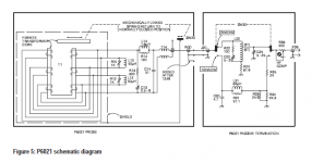
The current probe may work better and have more extended low frequency response with an optimized termination. Usually they want a low impedance termination. Below is the Tek P6021 as an example of a passive termination. There is a lot going on to get 50 MHz from it and the extended low frequencies. Too much for a casual DIY project but a subset may help.
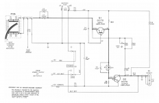
The HP456 is more in line what a practical DIY probe amp can be (it also dates from 1960) and it shows the direct drive into the inverting input. A decent opamp could replace the 2 transistors and eliminate the coupling caps.
Attachments
Hi Demian,
I will test this one to see if 30mA DC in the primaries leaves me with a working solution. Anything above 2H total should be enough so that means I can withstand a more than 50% reduction.
It's worth checking because if it works it's a zero investment, instant fix.
mike
With two winding you can check the change in inductance on one while driving DC in the other. Much easier than when there is only one winding. Also bring the DC up and down with the coils connected or you can get one hell of a snap+spark opening the link. Its how ignition coils work and it could fry your meter.
Keantoken,
The solution you propose is the second best in the paper I've referenced before, the best being the one proposed by Richard. I still think it is too complicated and prone to susceptibility issues that might be difficult to deal with in a real product that needs to pass CB tests.
Giorgio
It really isnt hard nor expensive after it is shown... like most things.
I did it in SPICE first and then applied for patent based on SPICE data and got it. I then had many made and are still made and selling well, I presume. A wide band shunt ac line filter.
[patent assigned to another company.]
THx-RNMarsh
Last edited:
Good to go Frank.

- Status
- Not open for further replies.
- Home
- Member Areas
- The Lounge
- John Curl's Blowtorch preamplifier part II