vacuphile queried whether I saved the results, but Murphy struck - I did lose some work files from that period through a typical computer misadventure,I spent some time, a while ago, playing with this - and it would be possible. The algorithms, and processing, need to be quite sophisticated but it certainly is doable. As a test case, I used an extremely overcooked, locally produced pop number - used as the theme tune for a TV show in fact - and manually played with parameters, using various criteria for judging the settings. The end "product" was vastly better in terms of the subjective impact, and certainly didn't appear to suffer distortion from the manipulation - the drums, which were buried under heavily compressed guitar sound, emerged unscathed and the production was now in far better balance.
 ; I also burnt it to CD, but haven't tracked it down yet, . However, I did find another example of my fiddling at that time while rummaging - this was Californication by the Red Hot Chili Peppers, a pretty notorious example of severe compression. I ended up making a track composed of a snippet of the compressed, original audio, followed by the results of my decompression efforts, and repeated this combination a number of times, to make it easy to compare the before and after - an ABABABAB type of thing.
So, https://dl-web.dropbox.com/get/Audi...ACjgf4R2lqciU77KzklEVc2xCJWW6rTJYJP6phmErXW1Q ...
Last edited:
Here is one US supplier: Triad Magnetics Product Specs They don't have your exact choke but they do have a 6H 200 mA inductor. It weighs 2 Lb (1 Kg) and is stocked at Mouser for $23 ea. You are pretty assured of continuous conduction with 6H. It also has a DCR of 150 Ohms. That translates into 15V before you get to the cap. And with a choke input supply the output voltage is approx .707 X the RMS voltage going in. However $80 for two supplies for just that part quickly gets the BOM in the uber premium range. And they are not wound with 6/9 copper even. I would look for a small shop that could make a bifilar inductor so you would have one chunk of iron for both rails. Use it in normal mode, common mode won't do much.
Hi Demian,
Thanks for the link.
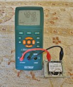
I checked in my transformer box this morning and found this. In my misspent past I have often used the secondaries of EI transformers as differential chokes. The drop is inductance due to partial core saturation does not present an insurmountable problem so long as the reduction is factored in.
I will test this one to see if 30mA DC in the primaries leaves me with a working solution. Anything above 2H total should be enough so that means I can withstand a more than 50% reduction.
It's worth checking because if it works it's a zero investment, instant fix.
The total DC resistance of the primary coils is about 200R.
I will be interested to check the performance of a choke vs 2 x 100R resistors. To be honest I would not expect much difference - especially as the supply will be housed in it's own grounded steel box so the actual pre-amp circuit will not be exposed to any EMR from the action of the diodes.
mike
Attachments
Last edited:
The core is nonconductive.Thanks. It is the slug out of a TV horizontal oscillator coil. Aha, so it's only good for 17k plus. I suspect diode snap to be far richer in frequency, so your core is probably dulling the waveforms. I did it as a first pass on something better than my Tek Hall effect sensor or my unlabeled "RF" one. This not very good one is giving me really nice examples of the problem areas. It is about 3 mV per mA at 120 Hz and gets better higher and then gets really funky. I have ordered some cores that should be more accurate, but the images are really quite interesting. Perhaps some rf cores that can run a coupla hundred Mhz. Note no absolute values given. We don't need no stinkin absolute values!! (BTY you almost gave away the reason why many ferrite cores "Sound Bad." That is also on my list of things to avoid. Have you ever measured how much distortion a ferrite core can actually make?)
I've dealt with solid iron laminated at .5 inch thick plates to .001 inch thick, ferrites, DC to over 10's of mhz, measured phase lag, amplitude, eddy distortions, gap field distortions, proximity losses...so I guess my answer is....yah.
But Jan I thought you knew my sense of humor!
Ah, that's what that was...
jn
First cores are due in today. I also have some .007" silicon steel coming in to punch a core or two. My maximum core size can be .375" dia. .5" ht and a center hole of .125.
I can punch it, deburr it, pickle it and then assemble the core all in house.
Now since you have measured core distortion, why do folks keep trying to use ferrites as noise filters?
I can punch it, deburr it, pickle it and then assemble the core all in house.
Now since you have measured core distortion, why do folks keep trying to use ferrites as noise filters?
But Jan I thought you knew my sense of humor!
I now officially hate you!
Jan
Now since you have measured core distortion, why do folks keep trying to use ferrites as noise filters?
Because of the ability to dissipate energy in the magfield around the wires. They are used quite successfully in industry to meet emission standards from the line.
I again ask, why was your core doing so many weird things at 10Khz?? I suspect that your layout may have contributed to that weird waveform, you're currents were not that large.
jn
I now officially hate you!
Jan
What took you so long? Welcome to the club, I'll send you a decoder ring.
jn
Because of the ability to dissipate energy in the magfield around the wires. They are used quite successfully in industry to meet emission standards from the line.
I again ask, why was your core doing so many weird things at 10Khz?? I suspect that your layout may have contributed to that weird waveform, you're currents were not that large.
jn
If I see those results from another core then it is worth looking. So far what is learned is there is a better approach to measuring diode noise with an application specific probe. Now to build a better one and calibrate it.
Also up is to measure the current vs voltage drop for the SiC rectifier. DC and pulsed.
When I get to showing distortion caused by common ferrite cores on clean signal, things get interesting. I still have my Fair-rite sample kit.
If I see those results from another core then it is worth looking. So far what is learned is there is a better approach to measuring diode noise with an application specific probe. Now to build a better one and calibrate it.
It'll be interesting. I hope you can tidy up the wind lay, close the loop to the coax. Also, you have lots of loop inductance by the layout of your bridge. It'd be great if your toroid is not so long, so you can drop the stray inductance.
If you give it a step current into a resistor, you should be able to see the transient thermal response on the vf if it's large enough. Problem is, its in the mv per degree c range, and your di/dt will really compromise what you can see.Also up is to measure the current vs voltage drop for the SiC rectifier. DC and pulsed.
When I get to showing distortion caused by common ferrite cores on clean signal, things get interesting. I still have my Fair-rite sample kit.
I'm still not comfortable with that conclusion, I suspect lots of setup artifacts.
jn
I'm still not comfortable with that conclusion, I suspect lots of setup artifacts.
jn
Not the same setup. Simple clean 60 Hz from my AP oscillator and test bench amplifier. AP looks at load resistor with and without bead. Also cable and bead in shielded enclosure with a grounded one end loop to RF spectrum analyzer.
Then there is the brown paper bag test, but I am sure you know how that one is done.
Not the same setup. Simple clean 60 Hz from my AP oscillator and test bench amplifier. AP looks at load resistor with and without bead. Also cable and bead in shielded enclosure with a grounded one end loop to RF spectrum analyzer.
Ah, switched the subject..ok..
I was talking about the distorted current waveform from your current probe. Something's wrong with your result.
jn

The situation was getting confusing, even for me, so I called Ed Simon. Five minutes and I NOW understand.
First of all, what is important primarily is the OVERSHOOT (upward pulse) difference between 'fast' and 'standard' diodes. Everyone, look carefully at the pictures in 54538.
It must be understood that several decades ago, we did not consider using high speed diodes for 60Hz operation. We thought they were only important for switching power supplies, where the working frequencies were 20KHz and above. I was fooled, until my colleague, Rick Miller showed me differently.
YET, it was difficult to get the information out, as Rick was not a known 'audio designer' so even his inputs to TAA would be resisted. (It happened to me with WW, back in 1971, in the same way.) So Walt Jung and I coaxed Ed Dell to show Rick Miller's findings. Since then, EVERYBODY knows about diode problems at 60Hz '-)
The situation was getting confusing, even for me, so I called Ed Simon. Five minutes and I NOW understand.
First of all, what is important primarily is the OVERSHOOT (upward pulse) difference between 'fast' and 'standard' diodes. Everyone, look carefully at the pictures in 54538.
Yup. That's the snap.
It is also important to understand the distinction between soft and hard recovery diodes as well. Hard recovery will cause the surrounding wire loops to oscillate.
Also, from the picture ed posted of his setup, notice how long the diode leads were, and how "unclean" the layout was from a high speed point of view.
The current probe also had lots of parasitics due to the enamel wire being so loose on the ferrite, and the very open wires to the coax also were an issue.
Part of my earlier job was to test diode recovery time, but my setup was geared towards looking at sub nanosecond recovery. I learned back then (80), how the wire dress and layout can change the waveform beyond recognition. As such, I still am concerned with the irregular waveform ed's current probe had at 10 KHz, something isn't right. I look forward to him making a good and tight one for further tests.
jn
Well JN, this is not the most important aspect of what Ed is measuring. It is the OVERSHOOT or lack of, that is the point.
I know exactly what is being discussed. The "overshoot" is the circuit inductance and current probe reacting to the fast turn off transition of the diode. It is called TRR, or transient reverse recovery.
The overshoot in the scope photo is not negative current, it is a combination of high current slew occurring within a circuit which is not designed for the slew rate being forced. edit: to wit, most of what is being called "overshoot" is actually artifacts of the circuit layout. That is why I mentioned the parasitics in a previous post.
Let me know if you wish to learn about the two standard methods of testing trr. One uses current thresholds, one looks at recovered charge..
jn
Last edited:
- Status
- Not open for further replies.
- Home
- Member Areas
- The Lounge
- John Curl's Blowtorch preamplifier part II