Could you take a look at my +/- 40 V schematic ?
I know resistor values must be recalculated, but I'm not sure about LM329 resistor placement.
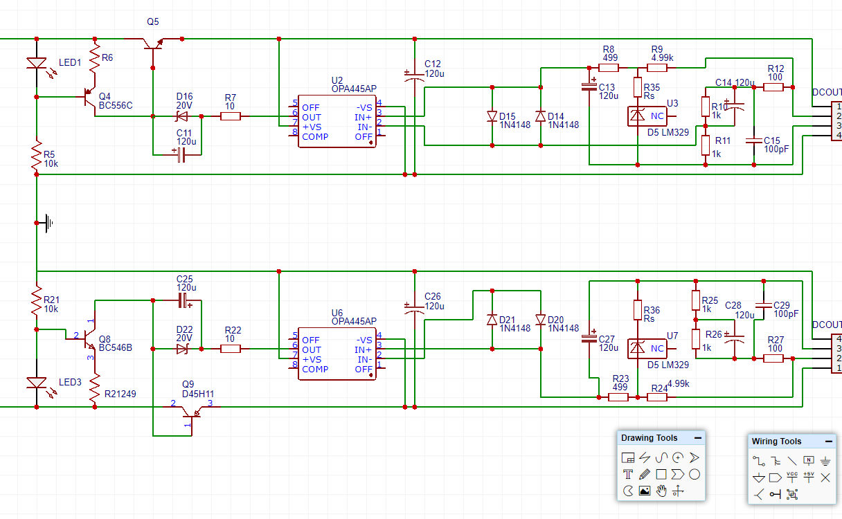
The ref diode is not biased correctly. What you must do is bias it with a resistor from the output. Then you take the output from the ref diode and send it to the +input, eventually through an RC filter.
U6 is missing the -input from the feedback network though.
That opamp is a bit slower as some of the lower voltage ones that are normally used. Should be no problem for performance but maybe stability is not as good. If that appears to be a problem, deleting C14 & C28 will probably fix it.
Jan
Last edited:
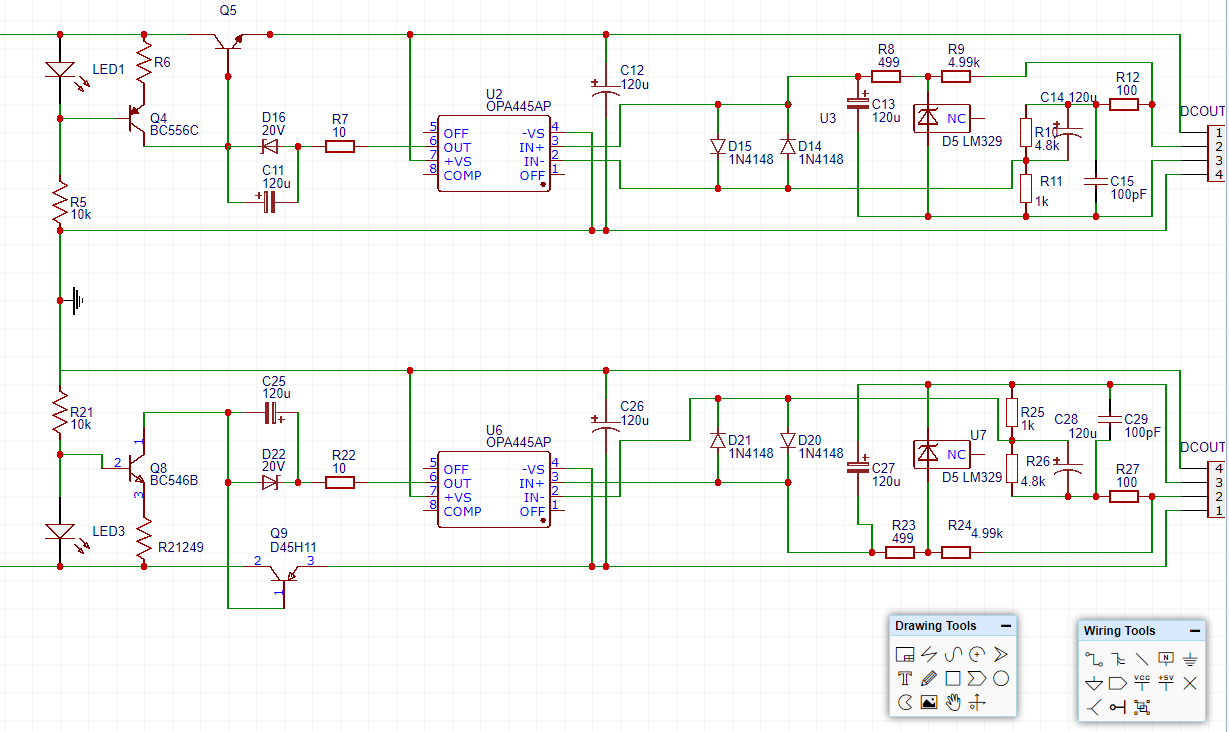
Wouldn't it be easier to increase R9 to bias the LM329 correctly and recalculate the divider R10,R11 for the wanted output voltage?
Yes, the bias resistor can be increased from 4.99k to 10k.
Of course the feedback resistors have to be recalculated for the new ration of 6.9V to 40V. So the resistor ratio should be 6.9 to (40-6.9)=33.1
2.2k and 10k would give a nominal 38.3V. Or 2.7k and 13k gives nominal 40.1V
Jan
Last edited:
")
Another good source for a ref diode is the LM4040 series, which are available in several voltages. The LM4040-5V is available even in 0.1% accuracy iirc.
For a 40V reg the 10V version would be nice, you'd only need a gain of 4.
Noise not as good, but the superreg has a noise filter on the ref anyway.
Jan
For a 40V reg the 10V version would be nice, you'd only need a gain of 4.
Noise not as good, but the superreg has a noise filter on the ref anyway.
Jan
Last edited:
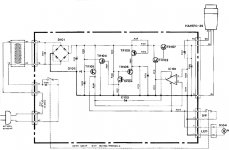
I‘m in the process to change one of my sr-boards to serve for 24 V outputs. I need it to feed my turntable. It has a 3 pole power connector, +24, sense, Ground. The sense line provides not 24, but 6V when working with the original part, so one part of the resistive divider is inside the turntable. I would prefer not to open it. Any idea how to apply this to the superreg? The circuit of the original device has 9k between pin 2 (of the sensing opamp) and ground, so I guess it‘s 27k inside the turntable. I‘d need a 12 V zener at the opamps output, choose an appropriate bias resistor for the ref-diode, and choose a lower voltage ref-diode, but can it work at all? What is the net-aquivalent restistance of the whole assembly? Or, if I form a resistive divider with another 27k resistor (pin 2 of the connector to ground in the diagram of post #1462), would it work or would I loose any meaningful regulation capability due to the now high-impedance node?
(Sadly, a SM for the table seems unobtainable. Another user tried by simply feeding the 24V while ignoring the sense line, and the table did not work at all. But this is OT)
I could rebuild the original, but if there‘s shortcut using an old superreg-board i prefer that.
(Sadly, a SM for the table seems unobtainable. Another user tried by simply feeding the 24V while ignoring the sense line, and the table did not work at all. But this is OT)
I could rebuild the original, but if there‘s shortcut using an old superreg-board i prefer that.
Attachments
LM329 is still an active part at LT ??
LM329 - 6.9V Precision Voltage Reference - Linear Technology
Patrick
LM329 - 6.9V Precision Voltage Reference - Linear Technology
Patrick
Jan,
diyaudio store does not stock super regulator pcbs
can I buy from you
Sorry, I don't have any. I turned over the complete design to diyaudio as 'donation' ;-)
Jason told me he has ordered more boards, so should be in stock again soon.
Jan
Note I don‘t have this device, just came across the schematic. And instead of cloning it (which would be possible) I want to use a superreg.
It can be replaced by a superreg; the only difference is that one of the feedback resistors (the top one) is actually in the unit. So you need to set the bottom resistor to the value for the required Vout, knowing that the top R is 6k iirc.
Because this is in fact 'remote sensing' you should fit the remote sense RC to avoid any instability due to long leads.
Jan
Hi Jan,
‚Remote sense RC‘ do you refer to R12/C15 (post #1462)?
Are you saying it has to sit close to the load (inside the table)? In this case I would have to open it anyway.
As i understand it, the sense line from table represents the net point of R9, R8, R35 and as such wouldn‘t be easy to adapt to the way the superreg sensing arrangement is done.
Or am I misinterpreting you?
R.
- Home
- The diyAudio Store
- Super Regulator