Hello to all .
I would like to use it to power the 8 volts in this DAC:
http://www.dddac.com/documents/dddac1794pbt_nos_ver51.pdf
in place of the tentlabs.
Do I have to make any changes or adaptations?
does anyone recommend me?
I would like to use it to power the 8 volts in this DAC:
http://www.dddac.com/documents/dddac1794pbt_nos_ver51.pdf
in place of the tentlabs.
Do I have to make any changes or adaptations?
does anyone recommend me?
Customizing the super reg
I get a lot of mail on this subject but I really am not set up to provide individual consulting. Most of the time you can ask here and there is almost always someone who has an answer.
To help, I have written up the process for customizing the output voltage, attached. If I figure out how-to I will also post it in the Articles area.
Jan
Attachments
Jan.didden
Jackinnj
Jack,
In you LA article, testing the sound of power supplies you mentioned that the Jung/Didden Super Regulator used in the bake off used a preregulator.
Will you share with us what that preregulator was?
I recently purchased the Jung/Didden Super Regulator PCB's here on diyAudio.
Will this regulator
LM317 / LM337 +/-1.5V~37V Adjustable Dual Voltage Regulator Power Board | eBay
come close to serving as a preregulator for the Jung/Didden Super Regulator?
Thanks DT
Triodethom,
I do no not believe that this is taking too much thought. The Super Regulator has used “off card” preregulators for 20 plus years. See the 2000 article for the improved regulator, specifically the bottom of page 12.
http://waltjung.org/PDFs/Improved_PN_Regs.pdf
What I am wondering about is if there is an improved 2018 version of the “off card” preregulators?
DT
Given that the lm337/317 generate about 2 magnitudes of noise greater than the Super Reg no. Some caps and a good diode set should be it will do fine. A damper on the diode bridge if you want some over kill. Don't over think this .
Agreed.
Jan
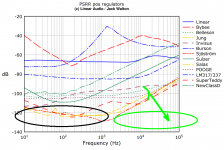
Since the graphs in the LA article clearly and unambiguously show that the awesome Jung/Didden Super Regulator's least-awesome feature is high frequency line rejection, I offer the respectful observation that any pre-regulator shenanigans should focus upon that.
Unfortunately, LM317-LM337 are particularly poor at HF line rejection, so (in my opinion!) they are rotten candidates for preregulating a Jung/Didden Super Regulator.
A few circuits that are excellent (in my opinion!) at HF line rejection include (i) properly damped LC filters; (ii) RF feedthru capacitors; (iii) capacitance multipliers / no-feedback Zener+BJT "regulators" using high-Early-voltage BJTs.
Fortunately, these latter circuits are generally very well modeled in LTSPICE. If LTSPICE tells you that circuit X is 20% better than circuit Y, in my opinion it's a very good idea to use circuit X instead of Y. On the other hand if the difference is less than 10%, skepticism of simulation accuracy may be warranted. Me personally, when simulation results are within 10%, I would flip a coin.
Since the graphs in the LA article clearly and unambiguously show that the awesome Jung/Didden Super Regulator's least-awesome feature is high frequency line rejection, I offer the respectful observation that any pre-regulator shenanigans should focus upon that.
Unfortunately, LM317-LM337 are particularly poor at HF line rejection, so (in my opinion!) they are rotten candidates for preregulating a Jung/Didden Super Regulator.
Also the LA article clearly and unambiguously says that the awesome Jung/Didden Super Regulator is bootstrap pre-regulated. All the testing of the Jung/Didden Super Regulator in that article is done with LM317-LM337 bootstrap pre-regulation.
A few circuits that are excellent (in my opinion!) at HF line rejection include (i) properly damped LC filters; (ii) RF feedthru capacitors; (iii) capacitance multipliers / no-feedback Zener+BJT "regulators" using high-Early-voltage BJTs.
Fortunately, these latter circuits are generally very well modeled in LTSPICE. If LTSPICE tells you that circuit X is 20% better than circuit Y, in my opinion it's a very good idea to use circuit X instead of Y. On the other hand if the difference is less than 10%, skepticism of simulation accuracy may be warranted. Me personally, when simulation results are within 10%, I would flip a coin.
Mark, I get the impression that you want so start over from scratch.
DT
I do think that the vintage 1995 Jung/Didden Super Regulator (without any LM317s or LM337s) is pretty darn good all by itself.
However if someone wants to improve it, I believe they can get much better HF line rejection than what a preregulator using LM317 or LM337 provides. Merely by replacing the preregulator with something better. Three possible candidates are mentioned in #1512 and I'm sure clever people can dream up many more.
I myself would not be horrified, if new and original circuit design work were necessary to achieve the greatest improvement. A brand new PCB containing brand new circuitry, that is connected upstream of the vintage 1995 Jung/Didden Super Regulator. Other people prefer not to design circuits themselves, for a number of reasons, and they would be horrified.
A brand new PCB containing brand new circuitry, that is connected upstream of the vintage 1995 Jung/Didden Super Regulator.
Remember the scene in "Blazing Saddles" in which Mel Brooks plays an Indian chief: "Oy, lassen sie gehen". You go girl!
Mark, you make some good points, but there is also the case of diminishing returns. I am sure it is possible to still improve on the current design (which was last updated in 2000 by Walt, not 1995), but the question is a) can you measure that improvement, and b) does it do anything positive for the circuit to be powered. 20kHz line rejection of 100dB may be nice, but what is the 20kHz line signal coming in?
I would argue that it is more productive to look to solutions like the SilentSwitcher for totally mains-independent power for small signal circuits, with a performance which may not be totally on par with the superreg, but still provide performance that is indistinguishable as seen from the performance of the circuit to be powered. Lets chuck that archaic transformer and it's bridge!")
Jan
I would argue that it is more productive to look to solutions like the SilentSwitcher for totally mains-independent power for small signal circuits, with a performance which may not be totally on par with the superreg, but still provide performance that is indistinguishable as seen from the performance of the circuit to be powered. Lets chuck that archaic transformer and it's bridge!
Jan
Certainly the instrumentation used in Linear Audio v.4, can't measure many kinds of improvements to HF Line Rejection, because the Rail Driver (used to inject a sine wave onto the Raw DC input) cannot drive more than 0.1 microfarads. See TAA 1/95 page 15 (on Walt Jung's website) for an explanation.
Fortunately, we know this. And we can arrange the series cascade of HF Line Rejection filters (located upstream of the Super Regulator, where the LM317 preregulator used to go), such that the first one has a teeny tiny input capacitance: less than 0.001 microfarads. This presents an especially easy load to the Rail Driver. With the Rail Driver working in its comfort zone, there is good reason to be optimistic that the complete instrumentation apparatus will be able to measure excellent Line Rejection at the right end of the plot (green oval), just as it already measures excellent Line Rejection at the left end of the plot (black oval).
Naturally I support the virtuous goal of chucking the transformer and its bridge. However a lot of the line level circuits I work with, dissipate several watts (at the chassis level), and would drain a battery unacceptably quickly. For example, discrete opamps running from +/- 24 volt rails, with 20mA of bias current. Shunt regulators. That kind of thing. So I think there are going to be 50VA R-core transformers in my boxes for a while to come.
_
Attachments
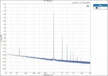
I started this quest a year plus ago attempting to improve the sound of a headphone amplifier, the overall SNR and THD+N were not bad for a tube. I posted a FFT here on diyAudio, a fellow poster asked what all the junk was on the noise floor. Averaging removed the real random noise. What remained were mains frequency/harmonics and intermodulation distortion spikes.
The test results show that the power supply is an integral part of the amplifier performance.
Yes Jan, get the transformers and bridges as far away as possible. Mark, lots of C L filtering then regulation including TentLabs filament regulators does do the job. See the attached FFT. (still working on the 60Hz spike. I unpluged everything but the analyzer and turn off the lights, the 60hZ spike remains unchanged.)
A note about managing tube noise:
Set the bandwidth filters on the analyzer, adjust the bench DC Voltage and adjust the operating point. It is amazing how adjusting voltage, current and watching the analyzer can optimize the distortion and noise performance. It is not just load lines on charts. This should also work with FET’s.
Thanks jackinnj for demonstrating what testing can accomplish.
DT
Attachments
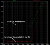
To encourage diyAudio members to horse around with circuit design themselves, I present below the result of 20 minutes worth of tinkering in LTSPICE. "Idea (iii)" from post #1512, was applied to a quick-and-dirty simulation model of a Super Regulator, just to get a feeling for whether the improvement might be large, or small, or even a degradation instead of an improvement.
LTSPICE says it was an improvement; the HF line rejection went from -40dB at 1 MHz (green trace), to -75dB at 1 MHz (red trace).
This is with no inductors and no RF feedthru capacitors, at all.
diyAudio members might be able to achieve even better HF line rejection in LTSPICE, if they decided to include inductors and/or feedthru capacitors.
_
Attachments
- Home
- The diyAudio Store
- Super Regulator