TDA1541A PCB already
Dear all,
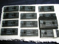
the first order of 12 pcs of TDA1541a S1 which I order from Holland is arrived. They all remove from old machine but unused.
The company told me was remove from Philips high grade parts wihch were repair stock.
I hadn't any instrument to test them but I made a simple hearing test compare with the standard TDA1541a. I only hear the background is more silience, little bit of punch dynamic was increase & little smooth sound stage. I can only hear will 6~8% inprovment.
But it actually quite good.
pls see the photos.
dear ftjandra,
If U like me to advise U, I will advise r-core than toroidals.
thanks
thomas
Dear all,
the first order of 12 pcs of TDA1541a S1 which I order from Holland is arrived. They all remove from old machine but unused.
The company told me was remove from Philips high grade parts wihch were repair stock.
I hadn't any instrument to test them but I made a simple hearing test compare with the standard TDA1541a. I only hear the background is more silience, little bit of punch dynamic was increase & little smooth sound stage. I can only hear will 6~8% inprovment.
But it actually quite good.
pls see the photos.
dear ftjandra,
If U like me to advise U, I will advise r-core than toroidals.
thanks
thomas
Attachments
Coulomb said:Thomas, how much for a pair of those S1's?
Secondly, if I just want to run 6.3VAC fillament do I have to do any of the tube mods or can I just solder all the sockets striaght in?
Regards
Anthony
Thomas any comments?
Re: //TDA1541A PCB Already
I did - about a month ago, but so far have not received an answer. Maybe my junk mail filter ate your message?
Peter
tube-lover said:For peter & SS1,agent.5,
pls email to me for detail of the kit.
thomas@diyaudiocraft.com
thnaks
thomas
I did - about a month ago, but so far have not received an answer. Maybe my junk mail filter ate your message?
Peter
AC Filament heating
Anthony, re. your filament change-I just lifted the pins in the end and ran tightly twisted cable directly to the tubes' sockets. Have you tried the 6c45pi's?
Have to admit I've done so many mods on the tube buffer, that it's not a lot like the original...Auricaps on the outputs [1mF], ordered Constant Current Supply kits from Kand K audio, AC filament heating...Rikens in the signal path...thank goodness the PCB quality is so fabulous.
Thanks to all people who have suggested mods...every one of them has made some difference.
I also noticed that Rockna is now doing a clock:
www.rockna-line.com/diy/uclock/clock.htm
// TDA1541A PCB already
Dear all,
Very long time that hadn't post any message for the kits.
I was too........oooo busy.
Now, a small amend for the kits.
I must did it( amendment for the kits) because I sell over 80 set of kits already.
Very thanks for all the Hong Kong diyer & oversea's support.
Dear Anthony,
U can directly use AC 6.3V for tubes filament. The sound will more active. I test this before but I was afraid that will increase teh noise. So I still advise use DC for tubes filament.
For the S1 single Crown. I cont' run in over ten days. very stable & hadn't any noise. After run in the sound stage was little bit smooth than standard 1541a.
I compare the R1, standard & S1. Some peopletold me that they trusted that the sound quality of S1 will be better than S2 because S1 was select by Holland Philips & was the highest grade in the previous production stage. The S2 was produced in Taiwan & was select in Taiwan. But this reason nobody can proved it right or not.
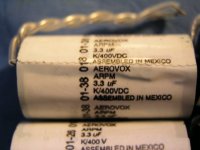
Peter, pls email to me one more time because I had only 10 set remain in hand. The small adjust for the parts was now will suggest the ERO MKP caps change to Aerovox 400V 3.3uf.
This caps was from USA military storage & still had telfon tube coated for lead out. I compare this cap with the ERO. ERO had very clear texture, this cap had better bass than ERO. The sound density will little much better than the ero but will not like Solen not clear low bass area sound.
this is my email.
thomas@diyaudiocraft.com.
Tim, although I can match the same date code of the DAC. BUt I still cannot make sure that the DAC was absolute match for their private clock in the DAC. so the jumper below the I2S was connect or broken to adjust the sound.
Another that will quite large effect the sound was the R43 & R52 of the tube buffer board. Standard is 470K 2W.
Pls try to adjust to 680K~Below1M. The sound will had large different. Adjust by your private Taste.
I suggest to use the RMA~ RMG. sure will much better. Not use Carbon film resisters, otherwise the sound will fog.
The last advise to amend was suggest by cmt42001 which use the 1.2V rechargeable NIMH cell for 6c45 bias. It only run in ~10ma. The cell most was over 1300mah. During working will be same time charge for the cell by the DAC. So it means one full charge cell can working over 1~2 months that not need to re-charge.
what is the different???
the deeper of the Bass is large improve. More detail HF, LF.
BTW, the different was large than U charge the caps.
Pls try.
For more detail ask cmt42001.
I was testing the DIY CD Drive. I use magnetic float. but some problems still not pass. I need your help!!!
thanks
thomas
Dear all,
Very long time that hadn't post any message for the kits.
I was too........oooo busy.
Now, a small amend for the kits.
I must did it( amendment for the kits) because I sell over 80 set of kits already.
Very thanks for all the Hong Kong diyer & oversea's support.
Dear Anthony,
U can directly use AC 6.3V for tubes filament. The sound will more active. I test this before but I was afraid that will increase teh noise. So I still advise use DC for tubes filament.
For the S1 single Crown. I cont' run in over ten days. very stable & hadn't any noise. After run in the sound stage was little bit smooth than standard 1541a.
I compare the R1, standard & S1. Some peopletold me that they trusted that the sound quality of S1 will be better than S2 because S1 was select by Holland Philips & was the highest grade in the previous production stage. The S2 was produced in Taiwan & was select in Taiwan. But this reason nobody can proved it right or not.
Peter, pls email to me one more time because I had only 10 set remain in hand. The small adjust for the parts was now will suggest the ERO MKP caps change to Aerovox 400V 3.3uf.
This caps was from USA military storage & still had telfon tube coated for lead out. I compare this cap with the ERO. ERO had very clear texture, this cap had better bass than ERO. The sound density will little much better than the ero but will not like Solen not clear low bass area sound.
this is my email.
thomas@diyaudiocraft.com.
Tim, although I can match the same date code of the DAC. BUt I still cannot make sure that the DAC was absolute match for their private clock in the DAC. so the jumper below the I2S was connect or broken to adjust the sound.
Another that will quite large effect the sound was the R43 & R52 of the tube buffer board. Standard is 470K 2W.
Pls try to adjust to 680K~Below1M. The sound will had large different. Adjust by your private Taste.
I suggest to use the RMA~ RMG. sure will much better. Not use Carbon film resisters, otherwise the sound will fog.
The last advise to amend was suggest by cmt42001 which use the 1.2V rechargeable NIMH cell for 6c45 bias. It only run in ~10ma. The cell most was over 1300mah. During working will be same time charge for the cell by the DAC. So it means one full charge cell can working over 1~2 months that not need to re-charge.
what is the different???
the deeper of the Bass is large improve. More detail HF, LF.
BTW, the different was large than U charge the caps.
Pls try.
For more detail ask cmt42001.
I was testing the DIY CD Drive. I use magnetic float. but some problems still not pass. I need your help!!!
thanks
thomas
Attachments
U can directly use AC 6.3V for tubes filament. The sound will more active. I test this before but I was afraid that will increase teh noise. So I still advise use DC for tubes filament.
So I can build the board without any of the tube mods?
Regards
Anthony
// TDA1541A PCB already
Dear Anthony,
yes, U can try to do this. after compare the different between standard or mod. Pls call me back the result .
Pls try to adjust the resisters that I advise.
Anthony, pls email the commerical invoice to me once again as previous that U need I fill & fax back to custom.
The first set of DAC kit that I post to U still hold in the custom.
I need to collect back but the local post office in Hong Kong need I send this received to them for follow up. Pls email once again to me.
thanks
thomas
I have an extra kit in hand due to some shipping and Customs issues. Thomas would like me to sell it for him to someone in North America, preferrably Canada, rather than ship it back to Hong Kong. Please contact me via email if you are interested, the funds would be sent to Thomas directly and when he confirms receipt of funds to me I will ship to the purchaser.
Regards
Anthony
Regards
Anthony
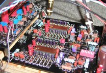
Well guys, I finished yesterday the DAC and SS output boards and I must admit that I'm pretty much impressed. Not only the quality of the board is first rate, but also the sound coming from this design is very good too. I'm scared to think what it will be like with all the mods I plan to go with.
Originally, I tried A grade DAC chips supplied with a kit and by itself it was fine already. Later, I placed S2 chips and it improved even more (smoother and refined).
And I'm pleasantly surprised that two chhips in parallel sound indeed better than a single chip. The difference is quite substantial.

C70, in loop filter, is listed (and supplied) as 0.33u. However, according to Monkey Sect (and also used by Pedja), it should be 3n3.
This capacitor should be soldered directly to pins of the receiver chip. The other two parts consisting filter, if possible, should be also very close to the pins. I removed mine from the board and mounted them directly underneath.
This capacitor should be soldered directly to pins of the receiver chip. The other two parts consisting filter, if possible, should be also very close to the pins. I removed mine from the board and mounted them directly underneath.
I was experimenting recently with bypass caps on the DACs and it seems like higher value sounds better. I had pretty good results with ERO MKT caps, and they actually sounded better than those famed Vishay 1837 type (although Vishays had rathe rlow value). With MKT 0.68u sounded more fuller and more pleasing.
Today, I tried BG NX Hi-Q caps (0.47u) and I have no doubts that those are right caps for the purpose. While MKT were OK, they sounded somewhat tense with slight coloration. BGs are on the other hand very smooth and open, with no perceivable coloration, and sound very natural. They are also convenient here, as their smaller size allows for a better (tighter) board layout.
Today, I tried BG NX Hi-Q caps (0.47u) and I have no doubts that those are right caps for the purpose. While MKT were OK, they sounded somewhat tense with slight coloration. BGs are on the other hand very smooth and open, with no perceivable coloration, and sound very natural. They are also convenient here, as their smaller size allows for a better (tighter) board layout.
Attachments
Today, I tried BG NX Hi-Q caps (0.47u) and I have no doubts that those are right caps for the purpose. While MKT were OK, they sounded somewhat tense with slight coloration. BGs are on the other hand very smooth and open, with no perceivable coloration, and sound very natural. They are also convenient here, as their smaller size allows for a better (tighter) board layout.
Very Cool, I just picked up 28 of that exact cap from PartsConnexion for my Board.
Hey Peter I have some time off right now as I am between contracts, I can run those baords down to you and you can show me how your projects are coming along.
Regards
Anthony
Peter Daniel said:I was experimenting recently with bypass caps on the DACs and it seems like higher value sounds better. I had pretty good results with ERO MKT caps, and they actually sounded better than those famed Vishay 1837 type (although Vishays had rathe rlow value). With MKT 0.68u sounded more fuller and more pleasing.
Today, I tried BG NX Hi-Q caps (0.47u) and I have no doubts that those are right caps for the purpose. While MKT were OK, they sounded somewhat tense with slight coloration. BGs are on the other hand very smooth and open, with no perceivable coloration, and sound very natural. They are also convenient here, as their smaller size allows for a better (tighter) board layout.
Peter Daniel said:Just to let you know that I'm taking this seriously, I placed my transport in a triple isolaton setup (concrete floor, acrylic stand, air suspended platform) in order to remove any coloration that might affect the digital source.")
Nice work Pete!
I'm glad you tried the BG NX-HiQ, I was also thinking about trying those, did you ever compare the 0.47uf against the 0.1uf BG's?
I don't know how the BG NX-HiQ would compare against wima mkp
I didn't try 0.1u, as the cost is still pretty high. I think higher value here gives fuller sound and more liquidity, while smaller value a bit cleaner presentation, but maybe thin at times. Really hard to say, but when I swapped 0.33u ERO MKT for exactly same type but 0.68u I think I preferred the higher value.
t. said:
I don't know how the BG NX-HiQ would compare against wima mkp
An easy way to compare those is using one of those caps at input coupling (digital section) and listening. You might install sockets for easy swapping.
I observed different signatures each time I changed those cap. I also like Caddock at input termination. For instance, tantalum sounded very dull (without air) and Vishay lacked definition.
- Status
- This old topic is closed. If you want to reopen this topic, contact a moderator using the "Report Post" button.