Cheers Pete
Like you said, the BG's have the advantage of being smaller.
So I guess even the direction of the Hi-Q's make a difference if used for the 14 decoupling caps") I actually thought you was joking when I first read the direction of the non polar BG's made a noticeable difference, when I tried it myself I was very surprised
I actually thought you was joking when I first read the direction of the non polar BG's made a noticeable difference, when I tried it myself I was very surprised
Do you use a small value cap on the -15v supply for the TDA1541S2's? I'm trying to find a nice cap to use there seeing as though it has an influence on the sound
Like you said, the BG's have the advantage of being smaller.
So I guess even the direction of the Hi-Q's make a difference if used for the 14 decoupling caps
I actually thought you was joking when I first read the direction of the non polar BG's made a noticeable difference, when I tried it myself I was very surprised Do you use a small value cap on the -15v supply for the TDA1541S2's? I'm trying to find a nice cap to use there seeing as though it has an influence on the sound
Peter Daniel said:I'm using there 10u BG N, but I still want to experiment more. I also tried BG N on digital supply pins, but to my surprise it seems like 10u OsCons sound better here.
I'm not using 0.47BG on pins 13 & 18, but here I used 4.7 N type only.
Very interesting, it seems that a lot of people do like to use Oscons for the digital supplies on the TDA1541 dac, do you use the SC or SP series Oscons?
I use 2.2uf polyprops for pins 13 & 18, the caps used here make a very big difference, some types I tried totally ruined the sound, even the value changed things.
I need to get some of those Caddock resistors you recommend as well to try.
Peter Daniel said:Those are the OsCons wit manetic leads, as such were supplied wit a board. BGs sounded a bit dry here.
I will experiment with the other two caps then.
Ok
Thanks again for sharing your findings, theres no end to this diy
loop filter network
Hello Thomas (and Peter Daniel ?),
at this moment i'm the lucky owner of those high quality PCB's. Really nicely done !
When checking all the components and your posts on this forum i noticed the componentvalues of the loop filter network.
In post # 29 Thomas mentioned the 1K, 0,22 uF and 3300P (R38, C45 and C70 respectively). And supplied with the PCB is a 0,33 uF for C70. Peter Daniel noted that later on and stated the CC70 has to be 3N3 (= 3300P) and not the supplied 0U33.
But whith C45 i have the same problem. Supplied is a 47N; in the list of components also 47N. But in the text on the forum you're talking of 0U22 ??
Can someone please bring light to this matter; i would appreciate that a lot.
R38 = 1K
C45 = 0U22 or 47N ?
C70 = 3N3
Thanks in advance. I hope i have my board up and running soon. Rogier and i (i bought 2 boards for us) will first experiment with just a transformer coupling and not use the tube-board. Of course we will share our findings on this forum.
With regards,
Reinout
Re: Wildmonkeysects Loopfilter
Clearing the confusion ???
Hi Guys,
My boards arrived a few days ago - Thanks Thomas.
I have done most of my DAC board and am now waiting for my BG NX Hi-Q - thanks for the research Peter - I hope that our audio tastes agree.
Anyone that read the first version of this post can forget it - I was counting the pins wrong...
mike
I was counting the pins wrong...
Good, because I was just about to look over my board
One thing to mention is that the digital and analog grounds are not connected on Thomas' board. If you run analog PS from the same as digital part (using 18-0-18 feeding points) it will work fine, but if you add additional PS for analog section with separate ground arrangement, you might have problem with getting 15V on DAC's supply.
It is my understanding that both analog and digital grounds should be always connected at the chip, and that's what I did with a piece of wire. It works fine now.
I need a little help
.
I have a few questions about the DAC board.
1) Peter - re above - what chip ?
2) My 75 ohm resistor was missing so I need to buy one - any suggestions what type ? would non-inductive WW be OK ? What would be better ?
3) Coil Winding - Is there a preferred method ? should the coils be bifillial ( or whatever the word is that sounds like that ) or what ?
What kind and gauge of wire do I need ? Is the type of wire critical ?
thanks in advance
mike
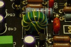
Here are some Photos of my progress so far on the Dual DAC Project.
Regards
Anthony
An externally hosted image should be here but it was not working when we last tested it.
An externally hosted image should be here but it was not working when we last tested it.
An externally hosted image should be here but it was not working when we last tested it.
An externally hosted image should be here but it was not working when we last tested it.
An externally hosted image should be here but it was not working when we last tested it.
An externally hosted image should be here but it was not working when we last tested it.
An externally hosted image should be here but it was not working when we last tested it.
An externally hosted image should be here but it was not working when we last tested it.
Regards
Anthony
Just ordered my kit!
I finally decided to bite the bullet and get in on one of the kits flying around this website after a year or more of sitting on the sidelines. It sucks continually reading about others having all the fun.
Paypal'd my money to Thomas this afternoon, so sometime in the next few weeks I should be in the groove
Can't wait to start
Just got my kit!
Just walked in the house to find a heavy package from our friend Thomas sitting on my desk. Eight days from pay to doorstep - thank you, Thomas!!!!!
This is like Christmas a month early. I don't have much experience with printed circuit boards, but as all the others have said - these things look absolutely amazing. Jet black with gold contacts, no exposed traces, perfect lettering - these look far better than any of the commercial components I've had a peek inisde. Not even close. You've got to feel the weight and strength of these boards.
BTW, the sheer number of components (resistors, caps, connectors, heatsink, etc) is a little intimidating for a beginner. All I can say is "A lot of pieces". A quick guess from the three full ziploc bags is 150-250(?). But the boards are so perfectly labeled that even I can feel(somewhat) confident of success.
I cannot imagine how much time it takes Thomas to seperate, count out, and package them all. But, it must take quite a while.
All I need to do now is track down a good 18V-0-18V/ 50VA transformer and an attractive case.
Anybody in the US have a good source for an affordable transformer and case?
Also, now that I have a look at these boards, I know I need to practice up on my soldering skills before starting the DAC. My normal sloppy style does not do them justice. I think I'll got get some perf board today and practice up for the next few days before starting on the real deal.
Thanks again to Thomas for a major sized effort in putting together this kit.
darkmoebius said:Paypal'd my money to Thomas this afternoon, so sometime in the next few weeks I should be in the groove
Just walked in the house to find a heavy package from our friend Thomas sitting on my desk. Eight days from pay to doorstep - thank you, Thomas!!!!!
This is like Christmas a month early. I don't have much experience with printed circuit boards, but as all the others have said - these things look absolutely amazing. Jet black with gold contacts, no exposed traces, perfect lettering - these look far better than any of the commercial components I've had a peek inisde. Not even close. You've got to feel the weight and strength of these boards.
BTW, the sheer number of components (resistors, caps, connectors, heatsink, etc) is a little intimidating for a beginner. All I can say is "A lot of pieces". A quick guess from the three full ziploc bags is 150-250(?). But the boards are so perfectly labeled that even I can feel(somewhat) confident of success.
I cannot imagine how much time it takes Thomas to seperate, count out, and package them all. But, it must take quite a while.
Can't wait to start
All I need to do now is track down a good 18V-0-18V/ 50VA transformer and an attractive case.
Anybody in the US have a good source for an affordable transformer and case?
Also, now that I have a look at these boards, I know I need to practice up on my soldering skills before starting the DAC. My normal sloppy style does not do them justice. I think I'll got get some perf board today and practice up for the next few days before starting on the real deal.
Thanks again to Thomas for a major sized effort in putting together this kit.
Re: Just got my kit!
darkmoebius said:All I need to do now is track down a good 18V-0-18V/ 50VA transformer and an attractive case.
Anybody in the US have a good source for an affordable transformer and case?
- Status
- This old topic is closed. If you want to reopen this topic, contact a moderator using the "Report Post" button.